

Download PDF | Introduction to Drive Clipping
Clipping, as the name suggests, refers to limiting or clipping the values of a signal that exceeds a particular threshold.
Typically used in random vibration testing, the threshold is expressed in terms of the signal’s standard deviation (σ).
For example, if a clipping value is set at 3σ, then any drive signal values are capped at a max of 3σ. EDM version 11.1 introduces an innovative clipping algorithm called Intelligent Clipping.
Intelligent Clipping modifies the drive signal to minimize the loss in dynamic range of the profile. The algorithm also massively reduces (-30 dB) the amplitude of high frequency content to the drive signal. This comparison is with respect to the drive clipping algorithm used in Crystal Instruments’ older implementation.
Why Sigma Clipping?
This feature prevents amplifiers from tripping when the input ranges of an amplifier are lesser than the drive signal required to achieve a target GRMS. For instance, to achieve a target GRMS of a given profile, sufficient drive is required from the controller to the amplifier. Each amplifier is capable of a certain input range and there are potential situations where an input range is insufficient to hit a target GRMS. In such cases, using clipped drive signals with reduced peaks and increasing the general power in the drive signal will prevent the amplifier from tripping. Hence, the new sigma clipping feature can be used to maximize the power rating of the shaker amplifier system without tripping the circuit or compromising the dynamic range of the control profile.
Test Configuration
A random vibration test was used to test the improvements in the drive. The purpose was to check the controller’s dynamic range with and without clipping by adding a -90 dB notch into the test profile. A standard configuration was used for the FFT parameters including block size, overlap ratio, etc. The test profile provided below was used in the test.
1.Test Profile

Figure 1. Test profile
2. Test Parameters
| Number of spectral lines | 1600 |
|---|---|
| DOF | 120 |
| Number of averages | 60 |
| Overlap ratio | 50% |
3. Other test details:
No shaker was used to conduct this test and the output of the controller was directly fed to the input channel.
This eliminates the effects of the shaker dynamics which can limit the controller’s ability to fully meet the profile demands.
Every shaker (which is a mechanical system) comprises of its own mass, stiffness and damping which can make it difficult to fully visualize the capabilities of the controller.
The profile used was aggressive and comprised of a 90 dB dynamic range requirement.
Results:
Users can analyze the histograms and auto power spectra of drive and control channels to visualize the effects of applying Intelligent Drive Clipping.
| Purple | Sigma = 3 with old clipping method |
|---|---|
| Red | Sigma = 5 or no sigma clipping |

Figure 2. Histogram plot to compare no sigma clipping and old sigma clipping
Observe the histogram plot in Figure 2, where a sigma clipping value = 3 is applied and the drive signals values are limited to 3σ. Although this was the objective, there are two drawbacks in the old sigma clipping method:
1. Loss in dynamic range: The dynamic range of a controller is the maximum and minimum value that can be controlled simultaneously. To expand further, consider Figure 3. Without sigma clipping, the dynamic range of the drive signal (measured by the presence of a notch between 300 Hz – 700 Hz), is higher by 35 dB when compared to the drive signal with a sigma clipping value of 3 using the old method.

Figure 3. Drive signals auto power spectrum
2. Addition of high frequency component to the signal: The consequences of limiting or hard clipping the peak values of a signal are the addition of high frequency components to the signal as shown in Figure 4. This is a huge drawback considering the resonance frequencies of the DUT could fall in these high frequency contents and potentially damage the DUT.

Figure 4. Drive signal auto power spectra for entire frequency range
To address these drawbacks, Crystal Instruments has developed an innovative algorithm to significantly limit both issues. Rather than hard clipping the signal, the spectral contents of the profile are considered for a more “intelligent” clipping process that still meets the original motivations for protecting the amplifier. In the following Figure 5, the dynamic range of the drive signals is much better (Δ30 db) between the old sigma clipping and new sigma clipping methods.
| Blue | Sigma = 3 with new clipping method |
|---|---|
| Purple | Sigma = 3 with old clipping method |
| Red | Sigma = 5 |

Figure 5. Drive signals auto power spectrum with new sigma clipping
Figure 6 shows a large reduction of amplitude in the high frequency and thus prevented damage to the DUT.

Figure 6. Drive signal auto power spectra for entire frequency range with new sigma clipping
Figure 7 reiterates the benefits of the new drive clipping method. Unlike the previous sigma clipping method, these results are a lot closer to the control signal without sigma clipping (Sigma = 5) in terms of dynamic range and a huge reduction in high frequency content to the signal.

Figure 7. Auto power spectra of control signal

Figure 8. Drive signal time stream with Sigma = 5 and a provided amplifier range
Consider Figure 9 with the aid of “Intelligent Drive Clipping” and a Sigma value of 3, the maximum RMS of the signal using the same amplifier range is 3.33 V and Power is 11.08 W. This corresponds to a 60% increase in the RMS of the drive signal.
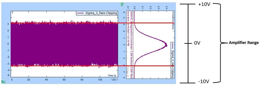
Figure 9. Drive signal time stream with Sigma = 3 and a provided amplifier range
Conclusion
The Intelligent Drive Clipping method developed at Crystal Instruments can help users achieve the target GRMS of a profile without tripping the amplifier system. This new method also significantly reduces the inherent drawbacks of hard clipping such as loss in dynamic range and the addition of high frequency components.
Users can also obtain a signal with a larger RMS within the provided amplifier range without tripping the amplifier.