Structural Dynamics Testing

Structural dynamics testing solutions include the high channel Spider-80X and the handheld CoCo-80X
Structural Dynamics Testing Applications
Structural Testing Capabilities
Roving Impact or Roving Response Hammer Testing
Random, Burst Random or Chirp Shaker Testing
Identify Resonance Frequency & Damping
Measure/Model Real or Complex Mode Shapes
Verify Linear Independence of Mode Shapes
Validate/Update Finite Element Models
Structural Testing Products
Many structural problems are solved by identifying the natural frequencies at which the structure resonates and the percent critical damping of each resonance. In some cases, operating vibration is reduced by changing an operating RPM or shifting a resonance frequency (by stiffening or mass-loading the structure) to avoid a frequency coincidence. Other problems are solved by applying a damping treatment to a structure that “rings like a bell”. Adding Isolation-mounts quiets floor vibration while appending a tuned vibration absorber can “split” a resonance to two acceptably different frequencies. All of these fixes are aided by applying a measured force to the problematic structure and measuring the ratio of its response acceleration to that force as a function of frequency.
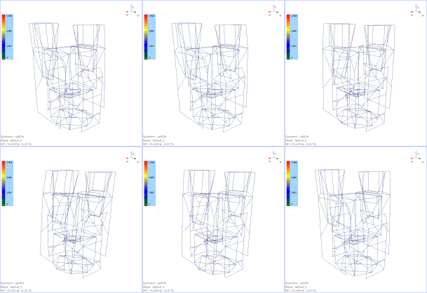
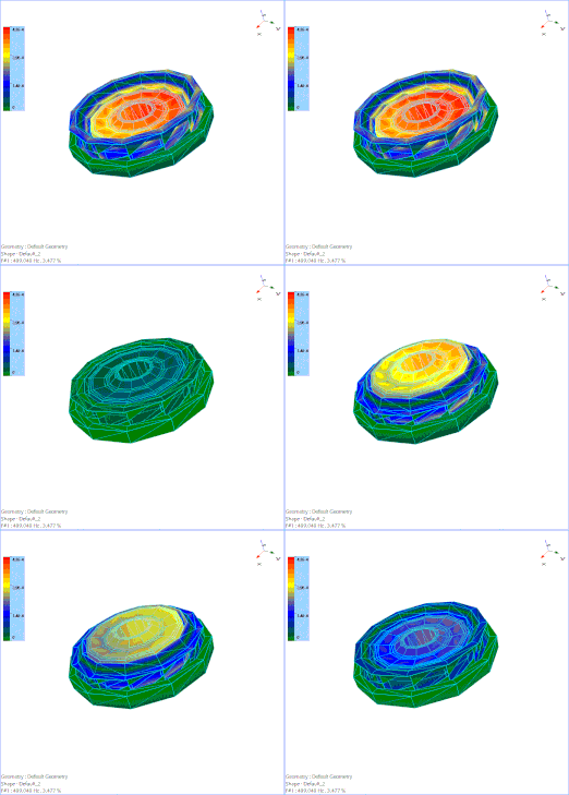
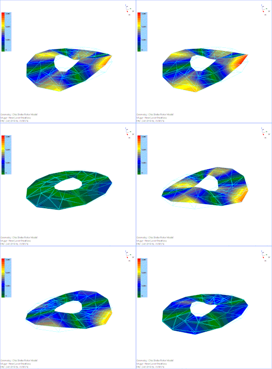
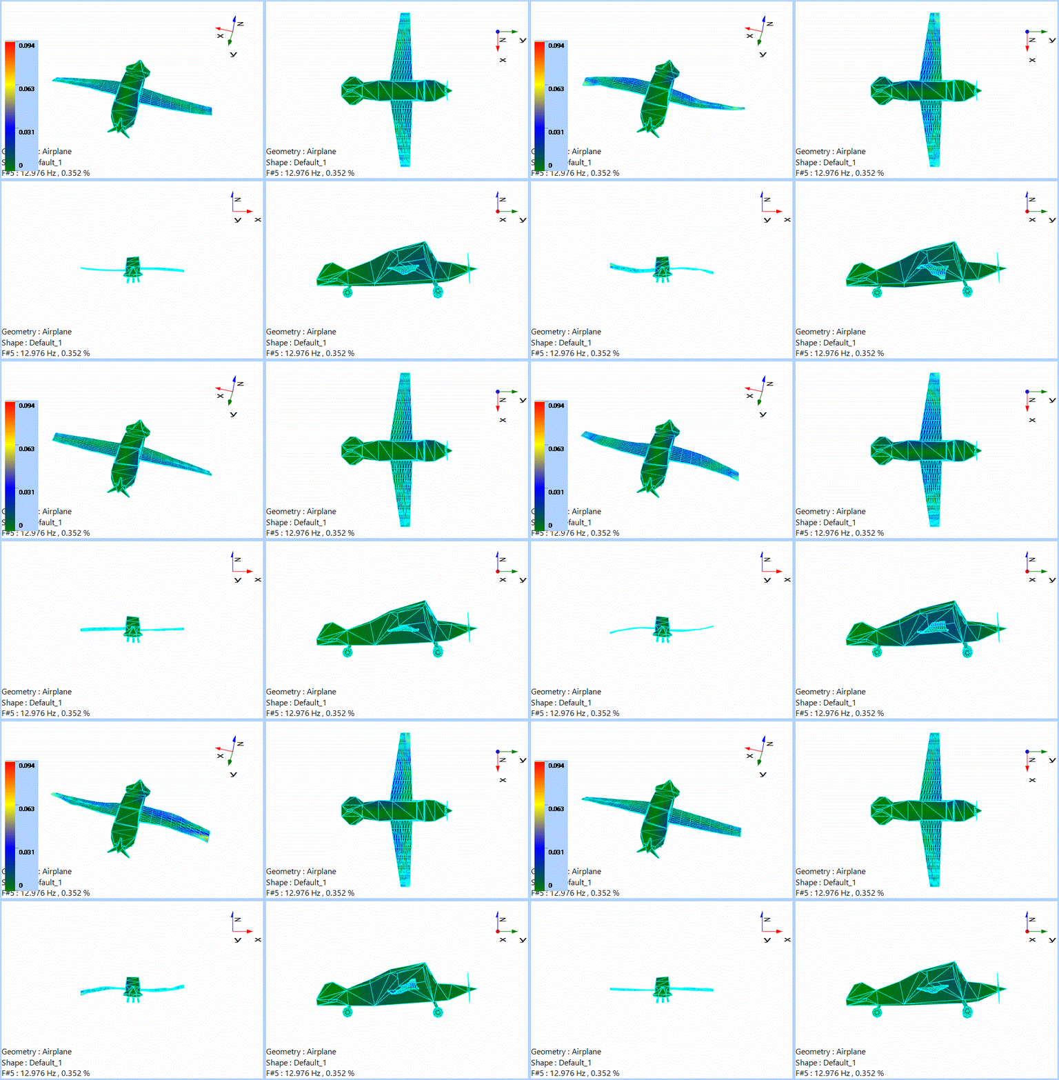
The vibratory behavior and stress distribution of a vehicle or civil structure can be predicted mathematically using modern tools like a finite element model (FEM). FEM is a truly powerful preliminary design tool, but its findings must always be test verified in the laboratory. Once prototype or production hardware actually exists; laboratory or field tests can confirm (or invalidate) a FEM. One of the most basic yet informative comparisons is the similarity between the experimental and analytic modes of vibration of the structure. Each mode consists of a resonance frequency, a damping factor, a modal mass and a mode shape or deformation pattern. Modes represent an important form of structural data reduction, because any vibratory motion the structure can exhibit can be expressed as a linear combination of the mode shapes. Since vibration is only of interest over a limited frequency range, this allows describing the motion at thousands of locations and directions (degrees-of-freedom or DOF) using only a small number of modes. This greatly reduces the number of complicated dynamic equations need to describe the vibration and to predict the effects of a structural modification or to model the attachment of the tested structure as a component of a larger structural system.
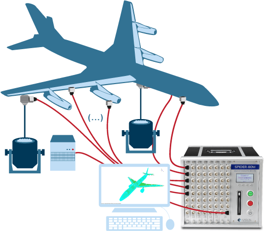
Modal properties can be identified from a series of acceleration/force Frequency Response Functions (FRF). An electrodynamic shaker may be used to excite the structure with a force measured by a force gauge at one DOF. An accelerometer at the same or a second DOF measures the response motion. A set of FRFs with acceleration measured at each desired DOF and the force measured consistently at one of them completes the required data set. This set may be achieved with a single accelerometer that is roved around the structure while a sequence of FRFs is measured by a 2-channel DSA. More efficiently, multiple accelerometers can be applied to the structure, one at each DOF of interest and all of the FRFs measured simultaneously by a high channel-count DSA.
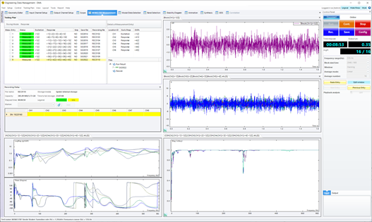
An alternative is to use a single accelerometer and substitute a force-instrumented impact hammer for the shaker, providing a compact kit for field use with a CoCo. While the data could be acquired by roving the accelerometer while impacting at a fixed DOF, most users prefer to exploit structural reciprocity; they mount the accelerometer at a fixed DOF and rove the impact DOF around the structure. EDM Modal provides the complete modal testing and analysis software which provides the modal parameters.


