
Spider-80Xi & Spider-80X 512 Channel Systems

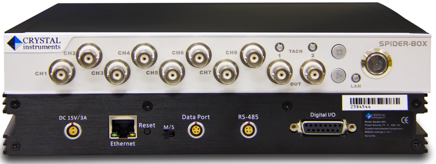
The Spider-80X is designed for applications in three fields: dynamic data acquisition, vibration test control, and machine monitoring. Each front-end features eight analog input channels and two channels that may be software selected as analog outputs for vibration control or tachometer inputs for the analysis of rotating machinery.
A single Spider-80X front-end is a complete two output controller with the same high quality patented dual ADC input technology of the Spider-81 series. The Spider-80X inputs provide single end/differential and AC/DC/IEPE coupling choices; charge mode is an available option that can be installed at the factory. The Spider-80X also provides the same time sync Ethernet connectivity and has 4 GB flash memory for data and program storage. Multiple Spider-80X front-ends may be linked together using the Spider-HUB Ethernet switch from Crystal Instruments. The data storage can be increased to 2 TB by adding a Spider-NAS mass storage device.
The Spider-80X front-ends are onsite swappable. Each front-end is metal-shielded. The user can quickly configure a system with an arbitrary number of front-ends.
The Spider-80SG strain sensing device has the same mechanical form factor as the Spider-80X. These two systems can combine into a system that measures various dynamic signals, including strains or other sensors requiring excitation. Multiple Spider-80X or Spider-80SG front-ends can be hosted in a 64-input chassis.
The Spider-80Xi is a compact version of Spider-80X with an extremely lightweight form factor. Featuring a 64 channel chassis weighing less than 10.5 kg, the Spider-80Xi can be carried in one hand and is optimal for field environment testing where portability is essential.
Like the Spider-80X, multiple chassis combine to create a system up to 512 channels, all sampled simultaneously. A dedicated massive storage hard disk (a 250 GB solid-state drive) allows the time signals of all input channels to record at up to 256 kHz/channel. Accurate time synchronization results in excellent phase match in the frequency domain between all channels, either on the same Spider front-end or across different front-ends. Real time FFT, octave, order tracking or vibration control functions can be enabled. The modular boards of the Spider-80Xi are installed at the factory and are not onsite swappable.
The Spider-80Xi system consisting of the 64 channel chassis is powered by AC power, at 100 to 240 VAC. The Spider-80Xi system consisting of the 32 channel chassis is powered by DC power, at 10 V to 22 V. The latter is also easily operable with an external battery pack. With the Spider-Battery, (developed by Crystal Instruments) a 32 channel Spider-80Xi system operates up to 4 hours without interruption.

A high channel count dynamic measurement system can be configured with multiple Spider-81 or Spider-80X front-ends.
High Precision Front-end Design
The Spider-80X/Xi analog input channels provide extremely high precision measurements. Each channel has single-ended or differential AC or DC input coupling. It can also provide IEPE (ICPTM) input mode (AC coupling with a 4 mA constant current from a 22 VDC source) for use with industry-standard accelerometers with built-in amplifiers. The ability to read TEDS (Transducer Electronic Data Sheet) identification from the attached transducer completes the channel’s compliance with IEEE 1451.4. Each channel provides an unprecedented dynamic range of 160 dBFS, detecting voltages as small as 600 nV and up to 20 V. This is accomplished by applying two 24-bit analog-to-digital converters to each channel and combining their outputs in accordance with our United States Patent number 7,302,354.
In the Spider-80X, built-in charge amplifiers are available. With Spider-80Xi the external charge amplifier, CA-08, can be used if charge mode is desired.
Black Box Mode
Black Box mode enables Spider-80X/80Xi operation without a PC. In this mode, a PC is used only to configure the control system before the system starts operation and to download data after the test is completed. During the test, the data acquisition system operates autonomously, according to a preset schedule or in response to external events such as input trigger or digital input.
Simple Network Connection
Ethernet connectivity allows Spiders to be located far from their host PC. This distributed structure greatly reduces noise and electrical interference in the system.

Spider-HUB

Spider-NAS
Spider-HUB Ethernet Switch
The Spider-HUB Ethernet switch made by Crystal Instruments supports the latest IEEE 1588v2 technology. The Spider-HUB guarantees time-stamping accuracy within 50 nanoseconds and can be configured for 1588v2 Master, Boundary Clock, and Transparent Clock functionality. Accurate phase match between all measurement channels across the modules are guaranteed. In a Spider-80Xi chassis the Spider-HUB is installed internally.
Spider-NAS Storage Device
The Spider-NAS (Network Attached Storage) is a dedicated storage device designed to work with Crystal Instruments Spider front-ends, including the Spider-80X and the Spider-81. Each Spider-NAS device supports up to eight Spider front-ends to collect both streaming time waveform data and spectral data. An Ethernet connection in back connects to a computer for data download and configuration. At the center of the Spider-NAS sits a removable 250 GB solid-state drive (SSD) with a storage upgrade option of 2 TB. This SSD not only provides greater shock protection than a classic hard drive but it also features a faster boot up time (less than 15 seconds) and is particularly energy efficient. In a Spider-80Xi chassis the Spider-NAS is installed internally.
Spider-80M MIMO Controller
The Spider-80M platform is based on the efficient Spider-80Xi architecture and is dedicated to MIMO VCS control and MIMO structural testing applications. Each Spider-80M chassis features 8 outputs capable of carrying out 6-degree of freedom MIMO testing. One Spider-80M chassis and multiple Spider-80Xi chassis can chain together to form a very large system with up to 504 input channels.
* VCS = Vibration Control System
* DSA = Dynamic Signal Analyzer
* EMA = Experimental Modal Analysis
*RCM = Remote Condition Monitoring
* MIMO VCS = Multi-input Multi-output Vibration Control System
* MIMO FRF = Multi-input Multi-output FRF analysis in EMA
| The Front-ends of the Spider-80Xi and Spider-80M Platform | |||||
|---|---|---|---|---|---|
| Front-end Types | Spider-80Hi | Spider-80Ci | Spider-80Gi | Spider-80SGi | Spider-80Ti |
| Max Sampling Rate | please refer to table below | please refer to table below | 25.6 kHz | please refer to table below | 2 kHz |
| Number of Inputs Per Front-end | 8 | 8 | 16 | 8 | 16 |
| Connector Type | BNC | BNC | 50 pin D-SUb | LEMO | 6-pin pluggable terminal blocks |
| Input Type | IEPE Voltage TEDS |
IEPE Voltage TEDS Charge |
Voltage Strain gage |
Voltage Strain gage Strain gage based sensors MEMS DC-based sensors IEPE |
3-wire RTD K-type thermocouple |
| Input Coupling | AC Differential DC Differential AC Single-ended DC Single-ended |
AC Single-ended DC Single-ended |
AC Differential DC Differential |
AC Differential DC Differential Bridge-Based Sensor In-line Charge Amplifier |
PT 100 (RTD) K-Type input (TC) |
| Sensor Excitation | 4.2 mA at 21 V for IEPE | 4.2 mA at 21 V for IEPE | +/-2.5 V, +/-5 V | +2.5 V, +5 V, +10 V, 22 V for IEPE | 10 μA to 1.5 mA RTD |
| Strain Gage Type | ------- | ------- | Quarter Bridges (Type I,II, 3 – Wire Quarter Bridge) Half Bridge (Type I,II) Full Bridge (Type I,II) Excitation voltage: ±2.5, ±5 |
Quarter Bridge (Type I, II) Half Bridge (Type I, II) Full Bridge Type (I, II) Excitation voltage: ±2.5, ±5 |
------- |
| Max Input Range | ±20 Vpk | ±20 Vpk | ±10 mV, ±100 mV, ±1 V, ±10 V |
±10 mV, ±100 mV, ±1 V, ±10 V |
400 Ohm (RTD) ±80 mV (TC) |
| Input Protection Voltage | ±220 V | ±220 V | ±220 V | ±40 V | ------- |
| Analog to Digital Converter per Channel | Dual 24-bit ADC | Dual 24-bit ADC | Dual 24-bit ADC | 24-bit ADC | 24-bit ADC |
| Cross Talk | < -100 dB | < -100 dB | < -130 dB | < -100 dB | ------- |
| Amplitude Accuracy | ±0.1% at 1 kHz 1 V | ±0.1% at 1 kHz 1 V | 0.1% typical, Less than 1.5% (up to 10 KHz), cable length up to 1000 ft (18AWG) |
±0.1% | ------- |
| Phase Match | < 1° up to 20 kHz | < 1° up to 20 kHz | < 1° up to 20 kHz | < 1° up to 20 kHz | ------- |
Channel count limitations per module for Spider-80Hi and Spider-80Ci at various sampling rates
| Sampling rate (khz) | Recording | FFT analysis | Max channel number per front-end | Dynamic signal analysis software | Vibration control software |
|---|---|---|---|---|---|
| 512 | to NAS only | No | 1 | Available | Not available |
| 256 | to NAS only | No | 4 | Available | Not available |
| 256 | to NAS only | Yes | 3 | Available | Not available |
| 204.8 | to NAS only | No | 8 | Available | Not available |
| 204.8 | to NAS only | Yes | 4 | Available | Not available |
| 128 | No limitation | Yes | 8 | Available | Not available |
| 102.4 | No limitation | Yes | 8 | Available | Not available |