
Spider-80M MIMO Vibration Test Controller
(Multiple-Input Multiple-Output Vibration Test Control)
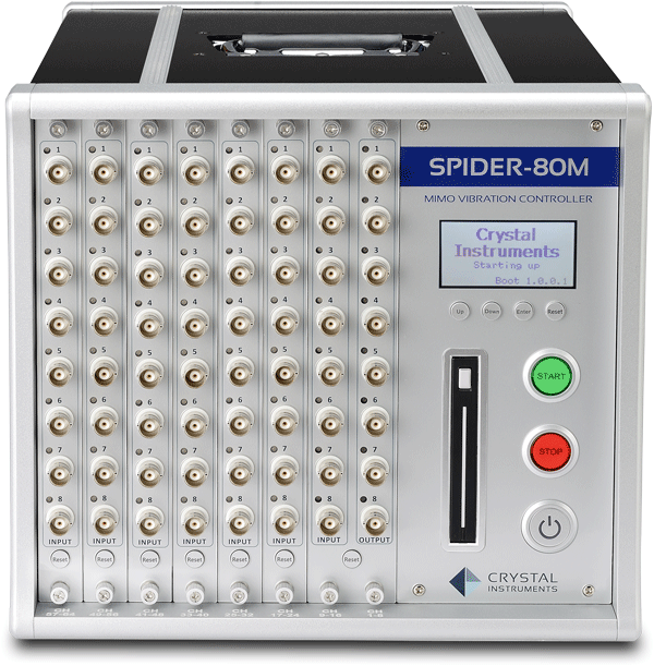
Spider-80M chassis contains up to 64 channels. Multiple chassis contains up to 504 input channels and 8 output channels
Based on Spider-80Xi Architecture
The Spider-80M platform is based on the efficient Spider-80Xi architecture and is dedicated to MIMO vibration test control and MIMO structural testing applications. Each Spider-80M chassis features 8 outputs capable of carrying out 6-degree of freedom MIMO vibration testing. One Spider-80M chassis and multiple Spider-80Xi chassis can chain together to form a very large system with up to 504 input channels.
Expand Channel Count
In a Spider-80M hardware chassis a master module with 8-inputs and 8-outputs will always be installed. This master module takes the space of two slots of Spider-80Xi module in the S80M-A35-8N chassis. Up to 6 additional Spider-80Xi front-end modules can be inserted to form a system with 8 outputs and up to 56 inputs.
The Spider-80M chassis can combine with multiple Spider-80Xi chassis to form a system with up to 504 input channels, all sampled simultaneously. Accurate time synchronization results in excellent phase match in the frequency domain between all channels, either on the same Spider front-end or across different front-ends. Channel phase match, even between separate Spider front-ends, is within 1.0 degree at 20 kHz which is suitable for high quality structural and acoustics applications requiring cross channel measurement.
Mass Storage
A high-performance removable 2.5-inch solid-state drive is used as storage media. When recorded, data will be written in the NTFS file format. Data is extracted from the Spider-NAS using Crystal Instruments software to transfer data to the PC. Alternatively, the solid-state drive can be physically removed and connected to extract data to the PC.
When it is shipped, a 250 GB solid-state drive is installed internally. The drive can be upgraded up to 2 TB. The solid-state drive performs very well in the high shock and vibration environment. A special error-checking algorithm developed by Crystal Instruments detects and avoids any errors that may occur in the data transfer and storage.
Time Synchronization
Through the Ethernet connection, multiple Spider-80Xi or Spider-80M chassis can be synchronized through the IEEE 1588v2 protocol. The synchronization accuracy is within nanoseconds when a specified network switch is used. The data acquired by all the measurement channels will be on the same time base. Phase match between channels across different Spider front-ends is within nanoseconds.
MIMO Vibration Testing Software Features:
Multiple-Input Multiple-Output (MIMO) Transient Time History Control
Multiple-Input Multiple-Output (MIMO) Shock Response Spectrum
Multiple-Input Multiple-Output (MIMO) Time Waveform Replication Control
Product Specifications:
Input Channel Specifications
Number of Input Channels per Chassis: 16, 24, 32, 48 or 56 when ordered with S80M-A35-8N; This is only factory configurable.
Maximum Input Channels per Spider-80M System: 504
Connector Type: isolated BNC
TEDS: IEEE 1451.4 compliant
Coupling: AC, DC, IEPE (ICP®)
Input Dynamic Range: 160 dBFS
Channel Phase Match: < ±1.0 degree up to 20 kHz across the whole system
Output Channel Specifications
Number of Channels: 8 channels per chassis
Connector Type: BNC
D/A Resolution: 24-bits
Sampling Rate: up to 102.4 kHz per channel, synchronized with input channels
Spider-80M Chassis
Size: 278.4 X 257 X 304 mm (W x H x L)
Total Weight: 12 kg with 56 channels configured
The chassis S80M-A35-8N can host:
1 Spider-80M module
Up to 6 Spider-80Xi front-end modules
Spider-NASi
1 Spider-H
| The Front-ends of the Spider-80Xi and Spider-80M Platform | |||||
|---|---|---|---|---|---|
| Front-end Types | Spider-80Hi | Spider-80Ci | Spider-80Gi | Spider-80SGi | Spider-80Ti |
| Max Sampling Rate | 256 kHz | 256 kHz | 256 kHz | 256 kHz | 1 kHz |
| Number of Inputs Per Front-end | 8 | 8 | 16 | 8 | 16 |
| Connector Type | BNC | BNC | 50 pin D-SUb | LEMO | 6-pin pluggable terminal blocks |
| Input Type | IEPE Voltage TEDS |
IEPE Voltage TEDS Charge |
Voltage Strain gage |
Voltage Strain gage Strain gage based sensors MEMS DC-based sensors IEPE |
3-wire RTD K-type thermocouple |
| Input Coupling | AC Differential DC Differential AC Single-ended DC Single-ended |
AC Single-ended DC Single-ended |
AC Differential DC Differential |
AC Differential DC Differential Bridge-Based Sensor In-line Charge Amplifier |
PT 100 (RTD) K-Type input (TC) |
| Sensor Excitation | 4.2 mA at 21 V for IEPE | 4.2 mA at 21 V for IEPE | +/-2.5 V, +/-5 V | +2.5 V, +5 V, +10 V, 22 V for IEPE | 10 μA to 1.5 mA RTD |
| Strain Gage Type | ------- | ------- | Quarter Bridges (Type I,II, 3 – Wire Quarter Bridge) Half Bridge (Type I,II) Full Bridge (Type I,II) Excitation voltage: ±2.5, ±5 |
Quarter Bridge (Type I, II) Half Bridge (Type I, II) Full Bridge Type (I, II) Excitation voltage: ±2.5, ±5 |
------- |
| Max Input Range | ±20 Vpk | ±20 Vpk | ±10 mV, ±100 mV, ±1 V, ±10 V |
±10 mV, ±100 mV, ±1 V, ±10 V |
400 Ohm (RTD) ±80 mV (TC) |
| Input Protection Voltage | ±220 V | ±220 V | ±220 V | ±40 V | ------- |
| Analog to Digital Converter per Channel | Dual 24-bit ADC | Dual 24-bit ADC | Dual 24-bit ADC | 24-bit ADC | 24-bit ADC |
| Cross Talk | < -100 dB | < -100 dB | < -130 dB | < -100 dB | ------- |
| Amplitude Accuracy | ±0.1% at 1 kHz 1 V | ±0.1% at 1 kHz 1 V | 0.1% typical, Less than 1.5% (up to 10 KHz), cable length up to 1000 ft (18AWG) |
±0.1% | ------- |
| Phase Match | < 1° up to 20 kHz | < 1° up to 20 kHz | < 1° up to 20 kHz | < 1° up to 20 kHz | ------- |