Shutdown Protection System (SPS) with Tracking Filters
Overview of Shutdown Protection System (SPS)
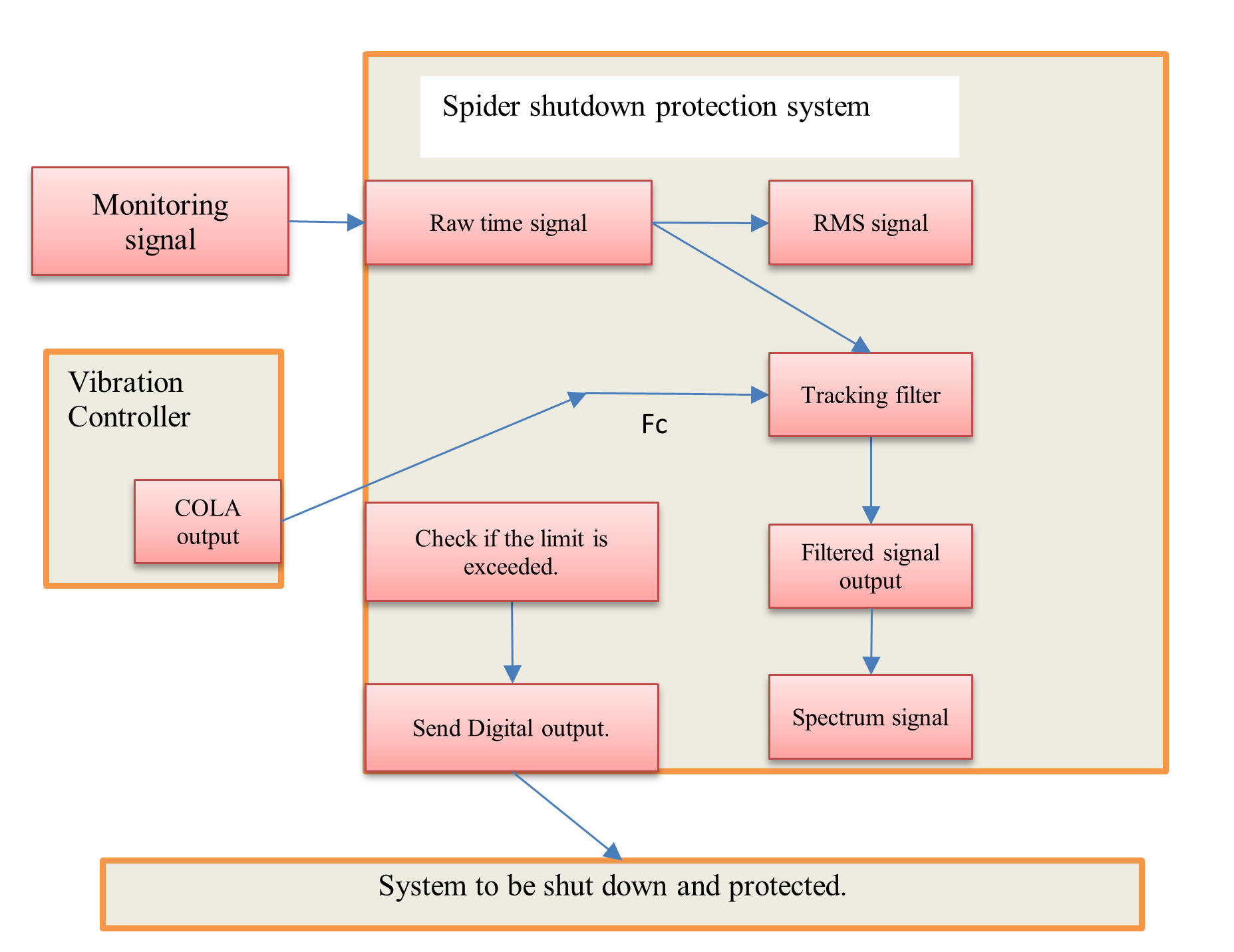
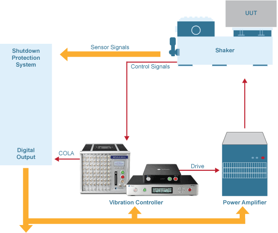
CI Spider systems featuring a digital input and output (DIO) interface along with EDM VCS software compatibility can run as a shutdown protection system. The main purpose of this function is to act as an independent hardware system to protect the shaker system. It can send out a shutdown digital output signal in less than 10 milliseconds based on various signal trigger conditions. It also includes various tracking filters that are identically implemented in the Sine controller.
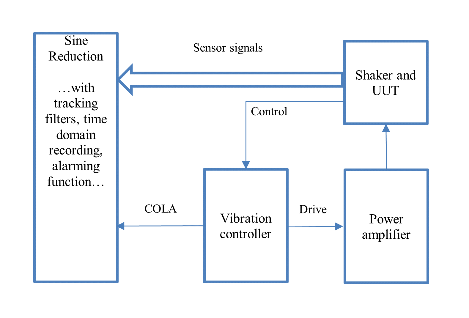
The traditional Sine Reduction functions are included in this package. Sine reduction acquires data to save and display in the form of Sine spectra traced to the sweeps of the COLA frequency. The COLA signal (Constant Output Level Amplitude) is a constant voltage sine wave which frequency tracks the Drive signal frequency during the Sine control test. It is the same frequency as the excitation frequency.
Connecting the Shutdown Protection System when tracking filters are needed
A fast shutdown logic can be added to Sine Reduction when using the digital output signal. This is now referred to as a Shutdown Protection System. The time domain trigger produces a SPS reaction time of less than 10 ms for a single module system and less than 20 ms if the trigger events are detected on the slave modules of a high channel count system.
When tracking filters are enabled in the SPS, which is common when a Sine test is conducted on a shaker, a COLA signal from the vibration controller will be fed into the shutdown system. The SPS will detect the sweeping frequency of the vibration controller which is then used in the tracking filters.
If the trigger condition is applied to the output of the tracking filter values, the reaction time varies depending on the setups of filter parameters. Crystal Instruments provides one of the best tracking filter implementations in the world.
The following are notable features of the SPS:
Works with any vibration controller with a COLA output
Hardware expandable to 512 channels
Multiple input channels simultaneously sample at up to 102.4 kHz.
Tracking Filters can be applied based on the frequency obtained from the COLA signal input.
Time Domain (raw time and RMS time) and frequency domain signals can be checked against preset threshold limits.
Exceeded thresholds can generate alarms or a digital output signal.
The digital output can be used to abort the vibration controller, shaker amplifier, or both.
Single hardware architecture to perform filtering, alarm checks, and digital outputs.
Single UI defines tracking filters, alarm thresholds, and sending digital outputs.
One hardware design for calibration, connections, and maintenance.
Hardware and software with the latest technology and wide scope for technological upgrades.
Simultaneous alarm monitoring for raw time, RMS of time signals, and the output of tracking filters.
Captures the part of the signal that triggered the limit, with user-defined pre-trigger and post-trigger duration
Allows continuous time data recording up to the drive storage limit (2 TB).

Threshold detection in a shutdown protection system
The SPS performance matrix includes the following aspects:
SPS reaction time
Amplitude accuracy of tracking filter output
Attenuation to the harmonics
Frequency Response of tracking filters: FRF of filter provides a more detailed description of the filter in the frequency domain.
Reaction time is defined as the time duration between the time that the input channel sees the event (such as time domain rising edge) and the time a digital output is sent out by the shutdown system.
When tracking filters are not used, the SPS can simply detect the time domain signals and compare them against the preset threshold limits. The reaction time can be as short as 10 ms. When a user wants to compare the output of tracking filters to the threshold, the reaction time can be as long as hundreds of milliseconds, which is totally dependent on the parameter settings of the tracking filters.
The amplitude accuracy of the tracking filter is determined by measuring the amplitude of tracking filter output, either in RMS or sine amplitude, when the SPS is fed by a fixed sine wave at a known frequency to the shutdown system together with the COLA signal that has the same frequency of that fed into the tracking filter. The measurement shall be conducted when the sine wave settles into a stable condition.
The attenuation measurement is similar to that of amplitude accuracy except that the sine wave frequency will be at the 2nd and 3rd harmonics of the COLA frequency.
The frequency response of tracking filter describes the amplitude and phase characteristics of the digital tracking filters when the center frequency of tracking filter is set at a fixed value. For example, the plot below shows the frequency responses of various tracking filters that can be enabled in the SPS/Sine Reduction system when its Fc is set at 100 Hz.
The table below describes a summary of the characteristics of various tracking filters that can be enabled in this software package.
| Signal source for trigger event | Fixed or Proportional | Comments |
|---|---|---|
| Raw time signal | --- | Shortest reaction time, 10 ms or less. No tracking filter |
| RMS of time signal | --- | Very short reaction time, 20 ms or less. No tracking filter |
| Output of tracking filter | Proportional Bandwidth Ratio | Fastest reaction time, great attenuation to the harmonics. High side lobes |
| Fixed Bandwidth | Reaction time depends on fixed BW. High side lobes | |
| IIR only -- Fixed Bandwidth | Reaction time depends on BW. Low side lobes | |
| Proportional + Fixed BW of IIR | Reaction time depends on BW plus Proportional portion. Low side lobes. High attenuation to the harmonics |
Sine Reduction is a sub-set function of SPS. It is simply a “slave” analyzer running the tracking filters and time domain recording that tracks the sweeping frequency of the vibration controller. SPS provides shut down functions using the digital output based on various trigger events.
The measurement results in the spectral domain of Sine Reduction will match with the measurement in a vibration controller. The spectral display shows how the measurement in the Sine Reduction (blue) matches the spectrum profile set in the vibration controller. These two signals are from two different hardware devices, one from the controller, one from the Sine Reduction system. The tracking filter setting is also displayed in the same plot below.

Two methods of gathering data during a test run are recording and saving.
Record: refers to the collecting of raw time stream data. Time stream data is recorded to the Spider internal storage, which can be later downloaded under Tools > Download from Spider Internal Storage. Signals must first be enabled in Setup > Measured Signals for them to be recorded.
Save: refers to taking an instantaneous snapshot of the calculated signals for a block of data (also known as a frame of data). Signals must first be enabled in Setup > Measured Signals for them to be saved.
Send Digital Output when the following selected limits are exceeded as trigger events.
To shut down a system with a digital output from the SPS/Sine Reduction system, the Send digital output when following selected types of limits are exceeded as trigger events must be enabled. When it is disabled, it runs as a Sine Reduction system.