
Define and Measure Dynamic Range
Sandeep Mallela (Director of Engineering) & Simran Parmar (Applications Engineer)
Download PDF | © Crystal Instruments 2025
Introduction
One of the breakthrough features that Crystal Instruments achieved is the outstanding dynamic range performance of 175 dBFS. This kind of performance has never before been achieved with such small, portable, and low cost devices. The main advantage of this high dynamic range is that it eliminates the need to adjust the input gain/range settings on the front end, thus simplifying the setup and measurement process. It allows for precise measurements of very small voltage levels while also being able to measure up to 20 V full scale values in the same measurement. This capability makes setup and testing more simplified in comparison with an instrument capable of either measurement of small voltages or large voltages. This document describes the concept of dynamic range, the different methods used to assess it, and how Crystal Instruments assesses dynamic range of the instruments.
Dynamic range is one of the critical performance specifications of a dynamic measurement system. If the dynamic range is too low, large signals will typically be clipped and distorted, while small signals are buried in system noise. This noise is inherent in the electronics associated with transducer elements and transducer signal conditionings. Maximizing dynamic range is paramount in instrumentation design, so that both small and large signals are measured accurately.

Full-Scale Dynamic Range (dBFS)
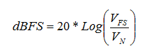
In Crystal Instruments’ tests, the most commonly used definitions, dBFS, Full Scale Dynamic Range, measured in dB is measured and applied. This is the ratio between the maximum measurement range peak to peak (VFS) and the RMS value of the system base noise (VN) given in dB. VN is usually measured with the input channel terminated so that a standard non-floating ground condition exists.
For a data acquisition system, the dBFS is a frequency dependent variable. The wider the frequency range the instrument uses, the smaller the dBFS. This is because the noise typically has a flat characteristic in its power spectral distribution. Therefore, the more of the spectrum that is included in the RMS calculation the larger the VN becomes. Consequently, the dBFS of the measurement is artificially improved by reducing the measurement bandwidth.
The dBFS is measured in either the time domain or the frequency domain with each giving different values. Time domain dBFS compares the noise signal summed over some broad range of frequencies in the RMS calculation. Frequency domain dBFS compares the noise signal energy at a specific frequency point. If the system noise has a flat spectrum, then the frequency based dBFS reports a lower value for VN and therefore a higher dBFS.

Figure 1. Plot showing the largest and the smaller amplitudes that can be measured
B1. Test Setup
Noise floor represents the smallest signal a dynamic signal analyzer can measure. The noise floor is measured by connecting a 50Ω resistor to each of the input channels. The 50Ω resistor represents a load with minimal noise characteristics of itself enabling the measurement of noise floor of the instrument. With any other type of load, including connecting sensors, the noise floor of the instrument cannot be accurately measured as the contribution of sensor’s noise is difficult to determine.
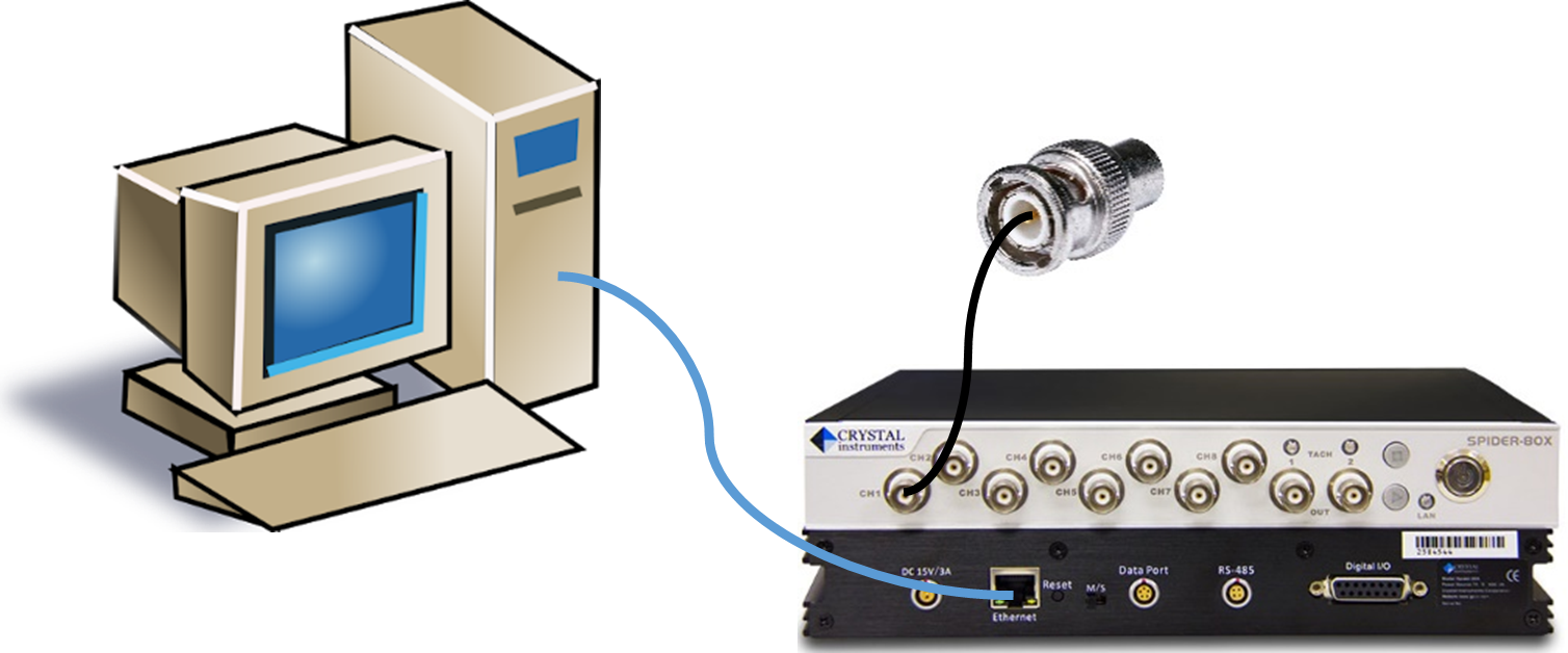
Figure 2. Test setup showing the connection of a 50Ω resistor to the input channels as a representative load
B2. dBFS Measurement in Frequency Domain
For a time-domain noise floor measurement, the results are highly dependent on sampling rate. This leads us to investigate the noise floor characteristics of the instrument in the frequency domain (which allows us to measure the noise level with respect to frequency). In the frequency domain, we can use the auto power spectral measurement and scale the display as dBFS.
For measuring the dBFS, the dB reference is set to the full range of the instrument. This will make the full range measurement of the instrument as 0 dB. Then the dB noise floor value will represent the noise floor with reference to the full-scale range measurement of the instrument which will be the dynamic range of the instrument. Most of the Crystal Instruments’ product including the Spider-80Hi, on which the tests have been conducted, has a full scaling range of 20 V. Therefore, the dB reference is set as 20 V.
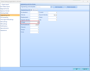
Figure 3. Test setting showing the dB reference set to 20V (full scale range of the instrument)
For measuring the noise floor, 25.6 kHz sampling rate is used for measuring the dBFS noise floor by identifying the frequency which has the worst noise performance.
The amplitude of the spectrum is displayed in dB.
The following analysis parameters are used:
Sample Rate: 25.6 kHz
Overlap: no overlap
Block size: 32768
Window: Hanning
Average: 256
Average type: Linear Average
The following plots show the noise floor of the Spider-80Hi v8.9 hardware with the noise floor in dB scale along with the plot showing the 20 V sine signal measured as 0 dB.

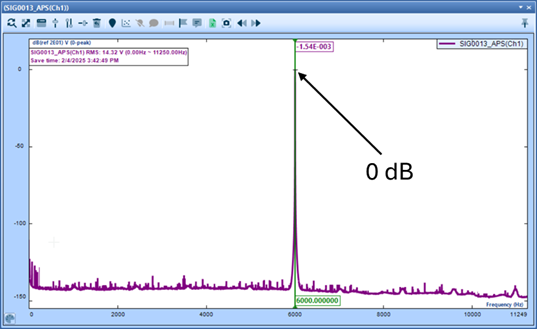
Figure 4. Plots showing the noise floor of the instrument and the peak measurable voltage signal
The plots shows that the dBFS Dynamic range of the instruments is higher than 175 dB.
How do CI products achieve such high dynamic range
Crystal Instruments achieves its very high dynamic range for all its measurement instruments by using a unique patented technology that uses two A/D converters in each measurement channel.
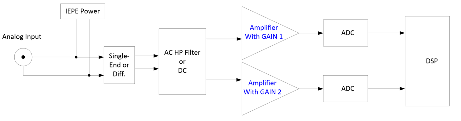
Figure 5. Dual A/D converter schematic
This unique technology uses two A/D converters per measurement channel. During the period of data acquisition, the time streams from both A/D converters are forwarded into the digital processor. The digital processor will pick the appropriate ones. With such high dynamic range of each input, the gain settings (voltage range settings) are very much eliminated.
Crystal Instruments was awarded a United States patent for this invention.

D. Conclusion
To conclude, dynamic range is not an absolute term since different manufactures have different methods of confirming the dynamic range. Hence, the numerical value will vary depending on which method was used to make the measurement. Using the definition of dBFS described above, Crystal Instruments products are able to achieve up to a 175 dBFS dynamic range.