
Ground Vibration Testing (GVT) Systems
 |
 |
 |
||
|---|---|---|---|---|
| Ground Vibration Tests (GVT) | Modal Measurements (Spider-80M & EDM Modal) | Modal Paramaters (EDM Modal) |
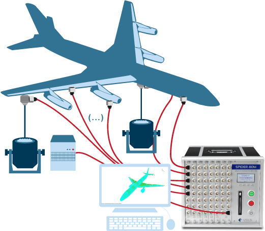
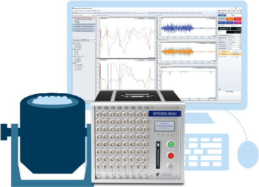
Multiple accelerometers are mounted on the aircraft and multiple modal shakers are used to excite the aircraft to obtain multiple-reference frequency response functions (FRFs). A high-channel count data acquisition system helps users efficiently process high channel test datasets. Several output excitation types (such as Random, Sine etc.) can be used for Multiple-Input Multiple-Output (MIMO) modal tests. Ground Vibration Testing (GVT) includes the modal analysis of an aircraft and its sub-assembly components to analyze and detect any changes to their structural properties. The modal parameters determined through testing are then used to validate the analytical models. The modal characteristics are also used to predict the flutter of the aircraft in order to create a safe flight envelope before flight operation. | ||
 |
 |
|
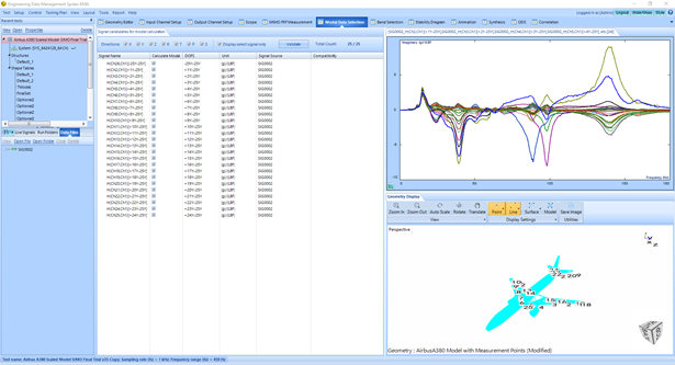
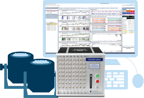
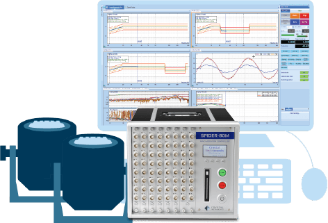
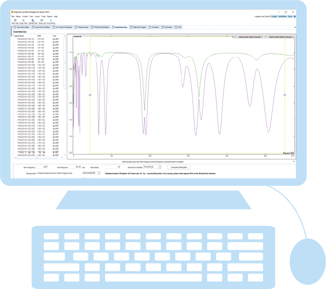
| A modal test of an aircraft is usually carried out in a single run to capture the response of entire assembly. A mesh grid with the measurement points is laid out and the geometry model (usually obtained from FEA or CAD model) is imported into the EDM Modal software. | The FRFs obtained between the excitation and the response points are overlapped to observe the dominant peaks in the desired frequency range. The imaginary part of the FRFs can also be overlaid to notice the phase relationship between the measurement DOFs. | Post-processing this data to curve-fit the measured FRFs assists in acquiring the natural frequencies, damping ratios and mode shapes of the complete airplane assembly. Good correlation between the experimental and FEA test results helps users validate the aircraft assembly and certifies it for other tests such as Normal Mode testing, etc. These tests declare that the aircraft is safe for flying. |
Single-Input Multiple-Output (SIMO) FRF Testing |
||
|---|---|---|
 |
EDM Modal SIMO FRF Testing includes a dedicated test setup and operation process flow using a single shaker to acquire FRF signals. Using a large channel count data acquisition system (i.e., Spider- 80X or Spider-80Xi), this shaker excitation method provides much higher test execution efficiency for the FRF measurements and minimizes the crest factor of applied forces. |
Software Features
|
Multiple-Input Multiple-Output (MIMO) FRF Testing |
||
 |
EDM Modal MIMO FRF Testing includes a dedicated test setup and operation process flow using multiple simultaneous shakers to acquire FRF signals. Using a large channel count data acquisition system (i.e., Spider-80X or Spider-80Xi), this shaker excitation method provides much higher efficiency and accuracy for the FRF measurements while minimizing local stresses on the test article. When using multiple shaker random excitation applications, the shaker-driving Source signals are guaranteed to be uncorrelated with one another. The Source Output type supports pure random (white noise), burst random, chirp/burst chirp, pseudo random, and periodic random. For periodic random types (pseudo random and periodic random), the delay block and cyclic block numbers can be set so that the structure exhibits steady-state response, allowing precise window-free analysis. Multiple shaker excitation is useful to separate and clearly identify repeated roots and frequency-proximate modes. With more than one reference shaker, multiple columns of the Frequency Response Matrix can be measured simultaneously. Combined with the poly reference curve fitting algorithm, the modal participation factor will help to isolate the repeated and highly coupled modes. |
Software Features
|
Multiple-Input Multiple-Output (MIMO) Sine Testing |
||
 |
EDM Modal Sine Testing includes a dedicated test setup and operation process flow using a single or multiple modal shakers outputting a sine wave to acquire FRF signals. The Source Output type is either Swept sine or Stepped sine. The sweep mode can be linear or logarithmic. The FRF signals of each measurement DOFs with respect to defined reference DOF will be constructed. The output drive level can be defined to run the test under no control strategy, or the response of a control channel can be specified to run the test in a closed loop. |
Software Features
|
Post Processing with Modal Analysis |
||
 |
Upon completion of the Modal testing, the set of FRF data is made available for the next step of Modal Analysis which provides the user with a complete arsenal of tools, from FRF data selection and parameter identification to results validation and mode shape animation. Mode Indicator Functions (MIFs) available in Band Selection aide in identifying repeated roots and closely-spaced distinct modes. The curve-fitters available in Stability Diagram facilitate in obtaining the modal parameters. Tools like Modal Assurance Criterion (MAC) and FRF synthesis provide means for validation of the modal parameters. |
Software Features
|
Correlation Analysis to Validate Aircraft Assembly |
||
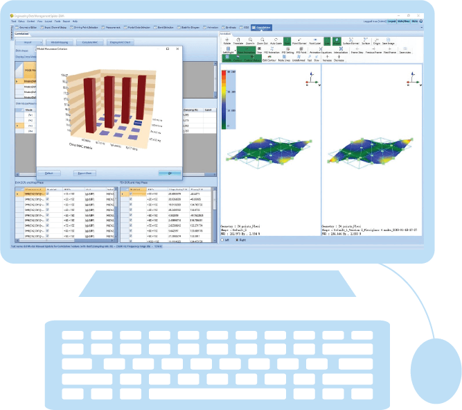 |
EDM Modal Correlation Analysis allows the user to correlate two modal models. The modal models can be EMA model, and/or FEA model. Comparing the experimental data with that acquired through finite element analysis helps in validating the test results. The geometry model and mode shape data from the FEA software or another set of mode shape data from EMA can be imported. A modal mapping procedure is executed to match the EMA and FEA models. After this matching procedure, the new mode shape information from FEA is interpolated and the FEA modal parameters are displayed alongside with EMA results. Finally, to observe the correlation between the results from two methods, a Cross-MAC matrix is calculated and shown. |
Software Features
|
Time Waveform Recording |
||
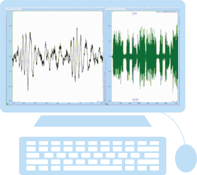 |
Establishing a time record of data is a critical requirement of vibration testing. Whether the application is ground vibration monitoring of railway activity or laboratory testing of a missile fixture, time recording can reveal important data. Times of peak activity, the overall vibration level at various times, the damping ratio, or other useful information is uncovered from acquired time data. Acquired vibration data might need synchronization with other data types. |
Time data acquisition requires users to understand the constraints and specifications of an application to select the correct data acquisition platform. To learn more, visit www.crystalinstruments.com/time-waveform-recording. |
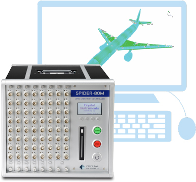
Spider-80M MIMO Test Controller |
||
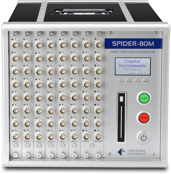 |
The Spider-80M platform is based on the efficient Spider-80Xi architecture and is dedicated to MIMO VCS control and MIMO structural testing applications. Each Spider-80M chassis features 8 outputs capable of carrying out 6-degree of freedom MIMO testing. One Spider-80M chassis and multiple Spider-80Xi chassis can chain together to form a very large system with up to 504 input channels. |
Software Features |