
You have 10 fingers, but that doesn't mean the input range has to be 10 volts!
Download PDF | James Zhuge, Ph.D. - Chief Executive Officer | © Copyright Crystal Instruments 2018, All Rights Reserved.
I’ve always wondered why some instruments in the market set their hardware input range to 10 V. Perhaps the hardware designer for these instruments possessed ten fingers and chose 10 V out of convenience. I can imagine their bosses eagerly approving the use of 10 V as well, because they too have ten fingers!

The use of 10 V could also be due to a time period in the history of dynamic measurement applications when PC based instruments dominated the market. During that time, it was convenient to supply a PC plug-in card with the existing PC power, which was +/-15 V. Typically, the input range swing performs well if its swing range is less than the power supply. As a consequence, the hardware engineer will choose 10 V as the maximum voltage input range.
Unfortunately, the 10 V range is a poor choice for dynamic measurement applications, especially when using an IEPE sensor. When an IEPE sensor is used, the voltage input swing can reach up to +/-15 V, which causes input circuitry overload problems for instruments using a 10 V range.
In the USA, IEPE-type accelerometers are very popular. With a rough estimate, over 80% of the sensors in the dynamic measurement market use IEPE-type sensors. In Asia, charge sensors still cover roughly 50% of the market because local sensor vendors are unable to produce high quality IEPE sensors, and because charge sensor technology is acceptable. Regardless, when IEPE-type sensors are used and the input range of instrument is limited to 10 V, the user may run into trouble with instrument overload.
What would be the best maximum input range considering the IEPE sensor overload problem? No doubt: +/- 20 V.
Below is an excerpt from the Spider system user’s manual elaborating on instrument input details:
Input Connections
The input channels of the CoCo-80X, Spider-80X and Spider-81 series are very similar in hardware design except the number of channels. Typically, the Spider-80X and the Spider-81 series have 2~16 analog input channels with an isolated BNC connector. The input range is ±20 V with single-ended, differential, IEPE, Charge Mode, and TEDS input type.
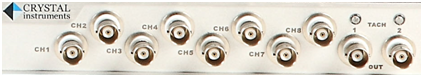
Figure 21:Spider-80X Input Channels
The block diagram for the inputs is shown above. The input chain has a number of components that switch in or out of the signal path. There is a calibration circuit used for internal calibration (see the separate Calibration Manual). There is also a charge amplifier and an IEPE power supply.
The front-end amplifier operates in single-ended or differential mode. In single-ended mode, the shield on the input jack is grounded, and the measured input voltage is referenced to this ground. In differential mode, the shield is not grounded and the measured input voltage is the potential difference between the shield and center terminal. After this initial amplification stage, there is an analogue high-pass filter for DC removal that is switched on only in AC input modes. After that, there is the final analog amplification stage, the Analog to Digital Converter, and the DSP processor.
The rest of the signal processing is done by the Digital Signal Processing (DSP) microprocessor. This processor specializes in the floating-point arithmetic used to process the input signal and generate an output.
The Spider-80X and Spider-81 series have charge mode as well as TEDS detection. They also adopt the patented dual A/D technology to achieve extremely high input dynamic range. A block diagram example of a front-end is shown below:
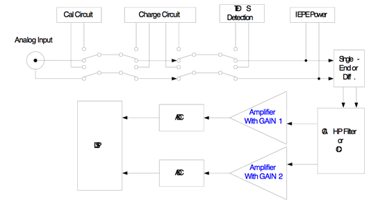
Figure 22:Typical Input Block Diagram (Spider-80X and Spider-81)
DC-Differential
In DC-Differential mode, neither of the input connections is referenced to the local ground. The input is taken as the potential difference between the two input terminals, and any potential in common with both terminals is canceled out. The Common Mode Voltage (CMV) will be rejected as long as the overall input voltage level does not saturate the input gain stage. Beware that very high CMV will cause clipping and may damage the input circuitry. Signals with a non-zero mean (DC component) can be measured in this mode.
DC-Single End
In single-ended mode, one of the input terminals is grounded and the input is taken as the potential difference of the center terminal with respect to this ground. Use this mode when the input needs to be grounded to reduce EMI noise or static buildup. Do not use this mode when the signal source is ground referenced or a ground loop interference may result (see the Grounding section below). This mode also allows signals with a non-zero mean to be measured.
AC-Differential
AC-Differential is a differential input mode that applies a low frequency high-pass (DC-blocking) analog filter to the input. It rejects common mode signals and DC components in the input signal. Use this when DC and low frequency AC voltage measurements are not required or when a DC bias voltage is present. The analog high-pass filter has a cutoff frequency of -3dB at 0.3 Hz, and -0.1dB at 0.7 Hz. Figure 24 shows the shape of the filter.
AC-Single End
AC-Single End grounds one of the input terminals and enables the DC-blocking analogue filter. Use this mode for non-ground referenced sources where measuring the DC or low-frequency components is not required. AC-Single End shares the same high-pass filter as AC-Differential.
When either of the AC input modes is used, there is also a digital high-pass filter, implemented in the DSP, with a user-definable cutoff frequency. Note that the analog high-pass filter is always active, even if 0 is set as the cut-off frequency for the digital filter.

Figure 24: AC Input Mode High-Pass Filter Shape
IEPE
All Crystal Instruments products support IEPE (Integral Electronic PiezoElectric) constant current output type input channels. IEPE refers to a class of transducers that are packaged with built-in voltage amplifiers powered by a constant current. These circuits are powered by a 4 mA constant current source at roughly 21 Volts.
IEPE accelerometers are available under several different brands including ICP® (PCB Piezotronics), Isotron® (Endevco), CCLD or Delta-Tron® (B&K), and Piezotron® (Kistler).
IEPE sensors are rarely used to measure DC or very low frequency signals. This is rarely a problem when measuring acceleration in dynamic tests. The IEPE input mode has the analog high-pass filter enabled with a cutoff of -3dB at 0.3 Hz and -0.1dB at 0.7 Hz.
Charge Mode
Some sensors provide a high-impedance charge output. Usually, these are high-sensitivity piezoelectric units that lack a built-in voltage mode amplifier (i.e. IEPE), allowing them to be used in high-temperature environments. The Spider front-end has a built-in charge amplifier that allows the system to read the output of these sensors.
The charge amplifier in the Spider converts the charge sensor output in picoCoulombs (pC) to a voltage in millivolts (mA), which is then input to the ADC. The sensitivity parameter in the software Input Settings sets the composite sensitivity from sensor output to engineering unit, so this process is transparent to the user. The analog high-pass filter has a cut-off of -3dB at 0.3 Hz and -0.1dB at 0.7 Hz.
For the Spider-80X, the input range is 40,000 pC. For the Spider-81 series, there are two gain settings in the charge channel, one with full range of 10,000pCand the other 49,000pC. Similar to that of voltage input mode, the user should try to maximize the input range of charge signals while ensuring no overload will happen. In other words, choose a charge sensor with higher sensitivity in order to achieve the best measurement results.
All versions of the Spider-81 are equipped with charge inputs. The charge amplifier is not available on the version 5.8 and older Spider-81B. It is available on version 7.x of Spider-81B.
Using an In-Line Charge Converter
An In-Line Charge Converter is an external device designed to convert the high-impedance source of a charge mode piezoelectric transducer to a low-impedance voltage signal by means of an IEPE powered signal conditioner. These units may be used with either quartz or ceramic charge-mode piezoelectric sensors.

Figure 25: The Charge Converter
When using a charge-mode sensor connected to an inline charge converter, use the In-Line Charge mode.
Notice that some in-line charge converters change the polarity of the signal. Do some initial testing to verify this before running a shaker test.
TEDS
The IEEE P1451.4 "Standard for smart transducer interface for mixed mode sensors and actuators" describes a mixed-mode communication protocol based on existing analog connections. Mixed-mode means that both analog and digital signals are sent over a single coaxial cable. IEEE P1451.4 also specifies the Transducer Electronic Data Sheets (TEDS) format where transducer-specific digital information such as transducer identification, sensitivity, location, calibration values, and other parametric data can be stored.
Front-end hardware that can communicate with TEDS sensors can read the digital data from the sensors and automatically configure the input settings. The Spider systems can use TEDS to automatically import the measurement quantity and sensitivity of connected sensors.
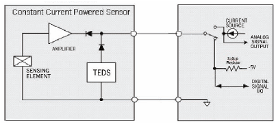
Figure 26: IEPE and TEDS Circuitry
Choosing the Correct Input Coupling
Accelerometers and other sensors that require the IEPE current source must have that mode enabled to operate properly. Note that the analog high-pass filter is enabled when IEPE is on, so measurements below 1 Hz cannot be made with these sensors.
For other types of sensors, measurements below 1 Hz are possible with the DC coupling modes. It is recommended that the control sensors in Shock tests use DC coupling.
The single-ended modes, which include IEPE, should be adequate for most situations, and are best for EMI noise rejection. However, if a non-IEPE sensor is used, and a ground loop problem occurs, then the input mode should be switched to differential. If a differential input mode cannot be used, then the ground of the controller should be tied to the sensor with a low-impedance conductor.
Matching Sensor Sensitivity to the Input Range
A special technique is used in CI products to achieve a very high dynamic range in the input channels. This patented technology uses two A/D converters for each input channel to achieve 130 to 150dB dynamic range. Refer to the 130 dB Dynamic Range CI whitepaper for more details.
With this technology, there is no need for multiple input range settings and measurements can be made over the entire range from a few microvolts to 20 volts. However, signal outputs from sensors should be as large as possible without overloading the input channels to maximize the signal to noise ratio. Too large of an input will cause clipping and distortion.
Do not exceed the input range stated in the specifications, usually ±20 V. For example, if you are doing a vibration measurement estimated to be 10 g RMS and the peak value of the test is assumed to go 5 times its RMS level, the sensitivity of the sensor should be smaller than 20V/50g-peak = 400 mV/g.
Choosing a sensor with too low sensitivity will cause the signals to be buried in noise. In the example above, if you choose a 4 mV/g sensor, the useful signal will be 100 times lower. The effect of noise sources such as EMI and ground loops will be much greater and the data will be unusable.
For charge input, the two ranges are 10,000pC and 49,000pC. For example, if the full charge range is 10,000 pC, you should choose a sensor that generates less than 10,000 pC with the expected peak excitation. But the signal should not be too small as to be buried in the noise.