Modal Analysis of Aircraft Propeller using EDM Modal
Download PDF | by Ziyuan Jiao | Graduate Student, M.S.E ‘18 | University of Michigan, Ann Arbor, United States | © Crystal Instruments 2018, All Rights Reserved
Introduction
Experimental modal analysis is the most fundamental method of determining the vibration behavior of dynamic systems. It is frequently utilized to estimate dynamical models and to retrieve modal parameters such as modal frequencies, damping factors and mode shapes from modal tests. In a previous test note, seven modes of a rectangular plexiglass board were investigated from a hammer impact test with roving excitation. The note demonstrated the capabilities of Crystal Instruments Engineering Data Management (EDM) software in handling the experiment data, computing the modal parameters, and animating the mode shape of a simple structure. This test note concludes the modal test result of a small aircraft propeller using a hammer impact test with the roving response method. The same modal analysis procedures were applied to the aircraft propeller to demonstrate EDM’s capabilities in discovering dynamic behavior of a complex structure.
Background
In 1932, Fritz Liebers (Liebers, 1932) wrote about the possible causes of propeller resonance vibration.
The propeller may have unstable vibration at a certain angular speed due to energy absorbed from the surrounding air.
Vibrations may be caused by the resonance between the natural frequencies of propeller blades and the frequency of the periodical discharge of vortices from the boundary layer.
Unequal impacts on blades due to an uneven field of flow during operation is the most critical issue and is very common among propeller airplanes, especially multi-engine airplanes.
The resonance vibration may cause fractures in the propeller once the amplitude of resonance vibration reaches a critical limit. Therefore, in practical applications, the dynamic properties of the airplane propeller are of great interest because of safety issues.
Airplane Propeller Model
The airplane propeller is modeled with 3 x 8 nodes on the top surface of each blade and has 48 measurement points in total. The inclined angle of each node was measured by the inclinometer and its local coordinates were entered into the system. (See figure below) Each node has its own local coordinate and measurements were taken based on its local axis. 12 nodes were modeled on central cylinder with equal space (6 on each face). Central cylinder is assumed as rigid body and won’t be measured in this test. The airplane propeller is suspended from an elastic band which ensures a free-free boundary condition. The hammer impact test with roving response method is used in this experiment. No. 50 node shown in the figure is the excitation point. And the accelerometer roves from node No.13 to No.60 to measure the +z (local) acceleration during the experiment.
Frequency Response Measurement
Frequency range of this test is set to 1.0 kHz, with a block size of 4096. With this setup, the response signal from accelerometer decays to zero within current block size, thus no window is needed. At each test point, EDM Modal records measurement data from the linear mean of 4 acceptable impact data. More number of frames could be selected to further attenuate the signal noise, at the cost of increased testing time.
In total, 48 FRFs are acquired after roving the accelerometer through all 48 nodes. They are plotted in semi-log plot shown in the following figure. From the plots, four major peaks can be observed between 100 ~ 600 Hz.
Modal Analysis Result
With the help of a Mode Indicator Function (MIF), the natural frequencies can be labeled. By eliminating rigid body modes at extremely low frequencies and insignificant modes at high frequencies, four significant peaks were found between 100 and 600 Hz.
Four modes are identified from the above stability diagram.
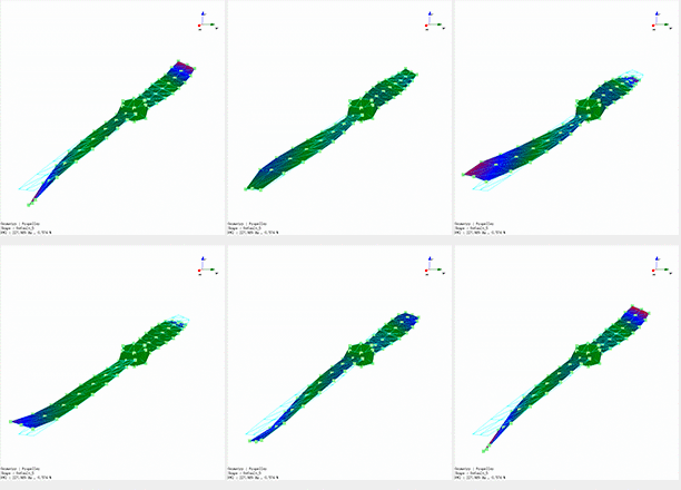
Mode shapes of each mode are shown below. Many settings such as changeable deformation amplitude, contour lines and plots, frame by frame animation can help customers to intuitively understand the different mode shapes.
Mode 1:
Both blades bend in same direction with no twist.
Mode 2:
Blades bend in opposite direction and twist along +x axis.
Mode 3:
Blades bend in opposite direction and twist along -x axis.
Mode 4:
Only blade tips bend in same direction.
Conclusion
The test note demonstrates first four bending and torsional vibration modes of a wooden propeller. Despite irregular shape and curved surfaces, EDM successfully dealt with measurement data, calculate modal parameters and generate mode shapes. It proves the EDM’s capabilities in discovering dynamic behavior of a complex structure and possible application in the field of aerospace.
References
Liebers, F. (1932). Resonance vibrations of aircraft propellers. Munchen and Berlin: Luftfahrtforschung.


