
Modal Testing of Endwindings
Download PDF | By Aakash Umesh Mange - Senior Application Engineer | © Crystal Instruments - March 2022, All Rights Reserved.
Two and four pole turbo generators have a relatively small stator bore diameter and the formed stators bar slot pitching requires a long endwinding outside the stator core, as shown in figure 1 and 2.
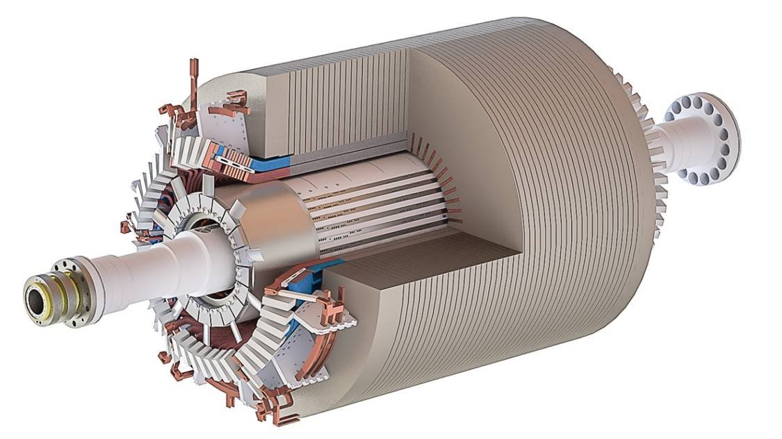
Figure 1. Typical Turbo Generator Assembly
The endwinding is supported against the high electromagnetic forces experienced during service and against electrical faults from the electrical supply system with external support brackets, bracing rings, and bracing between adjacent bars. Despite the stiffness this imparts to the structure, the overhung mass of copper winding will have natural resonance frequencies that are close to the forcing frequencies of line frequency and twice line frequency.
The 2-pole rotor magnetic field is a 4-node forcing function at a twice line frequency as illustrated in figure 3. Damaging levels of vibration can occur in the endwinding if it has a matching mode-shape and natural frequency close to a twice line frequency or for 4-pole machine 8 nodes. Figure 4 displays FEA plots for a cone to represent a simplified model of the generator endwinding.
Additionally, rotor vibration transmitted at rotational speed through the bearings may couple to the stator frame and core to the endwinding. Therefore the rigid body mode must also avoid the running speed frequency.

Figure 2. CE Endwinding Section and NCE with Support Brackets Removed

Figure 3. 2 Pole Generator Field Flux Pattern

Figure 4a. 4-node circular mode shape
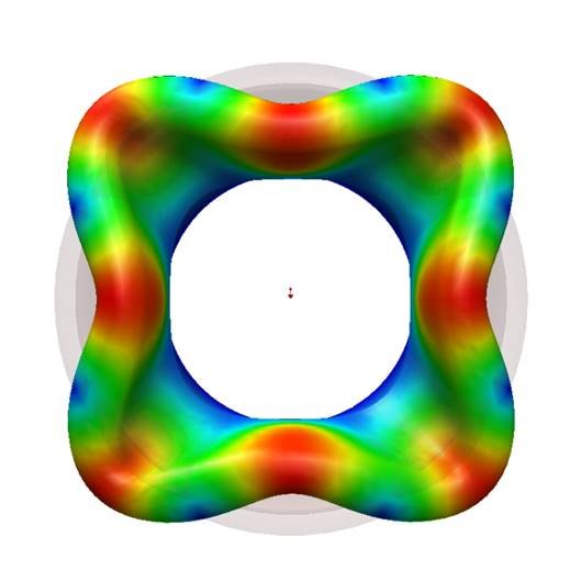
Figure 4b. 8-node circular mode shape

Figure 4c. 6-node circular mode shape
Modal testing and analysis is useful when obtaining the natural frequencies, damping and mode shapes of any structure. This study can be used to ensure that the resonances of the structure do not lie in the operating range. A modal test consists of exciting the structure with a force impact hammer or a modal shaker and measuring its frequency response function (FRF). The FRFs reveal the resonant frequencies (peaks) of the structure. The imaginary part of the FRFs (peak amplitude) at each location describes the mode shape for the associated resonant frequency and the damping of each mode determines the sharpness of each peak.
The Crystal Instruments CoCo-80X hardware and EDM Modal software was used to obtain the modal characteristics of a pole generator.
The CoCo-80X hardware system is equipped with eight software-enabled input channels. A unit initially purchased as a two channel CoCo-80X can be remotely upgraded to 4, 6, or 8 channels with a simple purchase. Each analog input is serviced by two 24-bit ADCs and a DSP implementing the cross-path calibration technology of US patent number 7,302,354 B2 to achieve a dynamic range better than 150 dBFS. Measured time histories can be recorded in 32-bit single precision floating point format and all subsequent signal processing is performed using floating-point arithmetic. 54 sample rates from 0.48 Hz to 102.4 kHz are provided with better than 150 dB of alias-free data.

Figure 5. CoCo Hardware System
The modal hammer and accelerometers for the roving excitation test were connected to the CoCo system to acquire time and frequency signals from the modal test performed on the pole generator. The recorded and saved signals are then loaded into the EDM Modal software.
A mesh geometry of the generator is created using the powerful and complete 3D modelling capabilities of the geometry editor function in EDM Modal.

Figure 6. Pole Generator Model in EDM Modal software
EDM modal software allows users to browse signals obtained from the roving hammer modal test performed on the pole generator. The time and frequency signals can be reviewed and any post-processing of the time data can be executed to acquire updated frequency signals within the modal software. If no post-processing is required, the FRF signals can be directly imported into the Modal Data Selection tab.

Figure 7. Review Measured FRFs in Modal Data Selection
Using the Band Selection tab in EDM Modal, various Mode Indicator Functions (MIFs) like Multivariate MIF (MMIF), Complex MIF (CMIF) along with Summation of FRFs can be used to identify the global modes of the generator from the measured FRFs.

Figure 8. Band Selection
Then, the Stability Diagram tab is used to curve-fit the data using the frequency domain p-LSCF (Least Square Complex Frequency) method to extract the modal parameters.
The Animation tab provides a visuals of the deformation experienced by the generator at these resonant frequencies. The results from EDM Modal are displayed in the following figures.
Figure 8a to 8c displays test data recorded from a ###MW 13kV 2 pole generator with 48 stator bars, clearly showing three mode shapes at the measured natural frequencies.

Figure 9a. 4-node circular mode shape

Figure 9b. 8-node circular mode shape
Figure 9c. 6-node circular mode shape
The natural frequencies, damping and mode shapes of the structure were identified using Crystal Instruments powerful handheld hardware and efficient structural testing software system.
Acceptance Levels
The endwinding can be considered as a revolved cone, cantilevered off from the stator core. To conduct a modal test, static accelerometers are fixed to the nose of one bar using beeswax and a roving hammer technique is used to sequentially excite each bar on each nose, using an average of at least 3. The data is recorded on a portable dynamic signal analyser.
Where access allows, measurement are also taken on inner parts of the winding as well to construct a 3D mode shape analysis.
A frequency span above 200 Hz is used to examine frequencies of interest since turbogenerators do not often exhibit higher modes than an 8-node in the frequency range up to 200 Hz.
Guidelines for frequency bands where the endwinding is to be free from harmful modes are provided by IEEE 1665[†]. The endwinding should be free of damaging vibration modes in the ranges 40 to 65 Hz & 80 to 120 Hz and should have an accelerance response of less than 0.045 g/N.
The exclusions bands extend above forcing frequencies because of winding stiffness and natural frequencies.