
Modal Testing on Hockey Sticks
Download PDF | © Copyright Crystal Instruments 2016, All Rights Reserved.
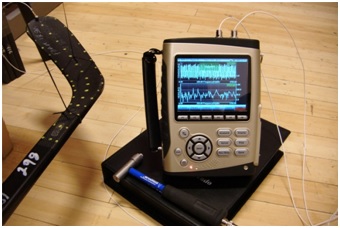
The modal response of hockey sticks affects their performance and usability in the hockey sport. In order to improve the performance of their sticks, one popular hockey stick manufacture used the CoCo signal analyzer to characterize this modal behavior. They used an impact hammer for excitation, an accelerometer to measure response, the CoCo for data acquisition, and ME’scope for the analysis. Hammer testing is a common way to measure the properties of mechanical structures. It involves striking the structure at various points to impart energy, and measuring its response at one or more response points. The resonant frequencies, mode shapes, and damping characteristics can be measured from this data.

Modal Analysis in ME’Scope
System Setup
PC with ME’scope 5.0 and Crystal Instruments’ EDM software
CoCo-80 4 channel signal analyzer
Impact hammer (IEPE powered by CoCo)
Accelerometer (IEPE powered)
Test structure: a hockey stick made of graphite epoxy
Excitation and Response Points
In this test, a fixed response point was chosen and the excitation was moved. Channel 2 captured the response at a fixed location and channel 1 measured the impact force at various locations on the stick. The number of measurement points was 12 to 120 points, depending on the resolution of the mode shapes that was needed.
Select Appropriate Configurable Signal Analysis (CSA) Project
For this test, a Frequency Response CSA was used on the CoCo analyzer. This will calculate the Frequency Response function between an excitation channel and a response channel. Since only response measurement was used, only two channels were needed on the CoCo.
Analysis Parameters
Block size/Line: 8192/3600
Average mode: Linear
Average number: 2, which means two measurements will be taken at each point.
Window: Force-exponential
This block size setting gave adequate frequency resolution for this structure. The force-exponential window is the best window to use for hammer tests.
The input channel settings were set for the sensors acttached to them. Channel 1 was connected to the impact hammer, so the sensitivity is set in units of mV/Newton or mV/LBF. Channel 2 was connected to the accelerometer with IEPE power enabled.
Analysis Frequency Range (Sampling Rate)
Choosing the correct analysis frequency range is important for this type of test, and it may take a couple iterations to get this setting right. If the frequency range is set to high, then the frequency resolution is spread too thin over the bandwidth for accurate measurement. If set too low, then important modes in the higher frequencies may be missed. In this test, the analysis frequency range was set as 1843.2Hz (sampling rate 4096Hz).
Setup Trigger
To capture the transient data from the hammer strike, a trigger was used on the CoCo. Trigger settings are changed under Acquisition Mode in the Param (F2) menu.
Modal Analysis in ME’Scope
For the impact hammer test, the following settings were used:
Trigger mode: Manual Arm Trigger
Trigger source: channel 1
Trigger condition: ch1 > high level (rising edge)
Trigger delay: around 5%
Trigger level: adjust to approximately half the peak value of ch1
Execute the Test
With all the parameters set, data was collected for each impact point. With the trigger on, the CoCo displays a trigger source window and waits for a trigger event. When an event is detected, a preview is shown, along with an option to accept or reject the input. Accepting it will add data blocks from each channel the running average of the power spectrum and frequency response calculations. The averaged data can then be saved by pressing the Save button on the CoCo.
Post-Processing
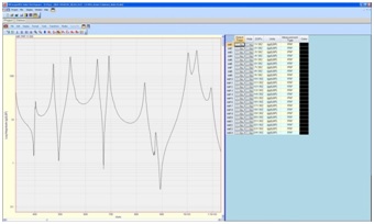
After the test was run and the data saved to the CoCo, it was downloaded to the computer and then exported in UFF format, which is readable by MEscope. In MEscope, a coordinate system was created to create a physical model of the hockey stick. The impact and response points were then set, and each point was associated with the corresponding data imported from the CoCo.
MEscope then performed a curve fit of the modal shapes, and calculated the resonant frequencies and damping characteristics. The end result was an animated model of the hockey stick structure.