
Pyroshock Data Acquisition Using Crystal Instruments Spider
Download PDF | By Sandeep Mallela - Director of Engineering | © Copyright Crystal Instruments 2019, All Rights Reserved.
Pyroshock or Pyrotechnic testing using simulation or explosive devices are typically used to test and qualify components for the aerospace industry. Components and methods used for acquiring Pyroshock data plays an important role to ensure that the acquired data is valid and not corrupted by several possibilities including the choice of sensors and the acquisition device. Several articles describing the selection of sensors and data acquisition devices to preserve the data integrity during Pyroshock data acquisition have been discussed including the popular article by Bateman [1].
ΔΣ Analog to Digital Converters (ADC) have been chosen to be the most ideal ADCs for Pyroshock data acquisition [1, 2] in addition to other hardware components. Advantages of using the Spider modules, which are built around ΔΣ ADCs, coupled with the right combination of sensors for faithful acquisition of Pyroshock data is discussed in this paper.
Pyroshock data that is most susceptible for corruption is the data that is acquired in the Near Field. Having excited using pyrotechnic methods, the amplitudes are typically over 10,000 g and the frequencies can range to up to several hundred KHz. The high frequency content of the data can excite the sensor’s resonant frequencies and could potentially generate a high output which needs to be effectively reduced.
In addition, data excited at all frequencies in a large frequency range (typical during Pyroshock tests) can produce undesirable ripples in the digital time data which will be discussed in the later part of this paper along with the methods deployed by Crystal Instruments’ Spider modules to reduce the ripple effect.
Selection of Accelerometers
The selection of accelerometers in the most important task for pyroshock data acquisition. The high frequencies generated could easily reach the resonant frequencies of crystals for Piezo-Electric (PE) accelerometers which can, at times, produce high voltage outputs that saturate the sensor and input channels of Spider modules. Once the signal from the accelerometers or the inputs are saturated, the data gets clipped and the true data is permanently lost. Resonant frequencies of PE sensors ranges from 80 KHz – 350 KHz, which easily excites the sensors during most pyrotechnic methods.
Spider systems are been designed to work in the range of -20V to +20V which helps the Spiders’ input channels avoid saturation in most scenarios. The sensors typically get saturated before the Spider input gets saturated. Even though the Spider’s input channels are not saturated, saturating sensors also causes undesirable data corruption which cannot be recovered, rendering PE sensors undesirable for Pyroshock data acquisition applications.
Piezo Resistive (PR) Accelerometers on the other hand have their resonant frequencies in the MHz range, which are less susceptible to excite at their resonant frequencies and thus generating lower amplitudes at their resonance avoiding and sensor saturation.
Spiders are equipped with analog anti-aliasing filters that filter out the high amplitude resonant signals before these signals reach the ADC (Analog to Digital Converter) and prevents the ADC from getting saturated.
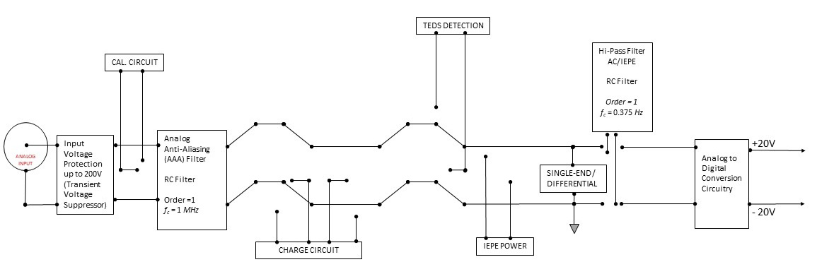
Figure 1: Analog pre-conditioning circuitry of Spider
Figure 1 shows the analog pre-conditioning circuit of the Spider modules. The first order Analog RC filter with a cut off frequency of 1 MHz should effectively reduce or eliminate the amplitudes coming in due to the resonating sensors.
Before the signal reach ADCs, another first order RC anti-aliasing filter (Figure 3) helps to further remove the signal components above 1 MHz.
Aliasing and Useful Band Attenuation:
Another major problem that causes data corruption is aliasing. Aliasing occurs when data with frequencies higher than half the sampling rate (fs/2) are present before the analog to digital conversion. Due to insufficient sampling points, these analog frequency components get misrepresented as data below fs/2 adds false data and causes data corruption.
To avoid aliasing, sharp analog filters with many poles must be used effectively eliminate the frequencies beyond fs/2. These high order sharp analog filters are associated with ripples in the pass band and non-linear phase response that causes data corruption in the pass band.
To avoid a ripple in the pass band and non-linear phase, a low order IIR filter is desirable when the frequency response has a gradual slope. When using these, depending on the selection of cut-off frequency, either the stop-band attenuation is insufficient and thus causing data corruption due to aliasing or the attenuation starts in the pass band itself is causing data corruption by attenuating the frequencies of interest.
An ideal approach would be to send all the passband frequencies unaffected and to suppress all the stop band frequencies. Over-sampling by several magnitudes while employing a filter with low order and ideal characteristics would resolve the existing issues and ensure data reliability for the frequencies of interest.
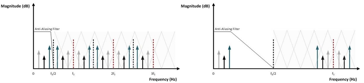
Figure 2: Oversampling to avoid aliasing while filters with desired frequency and phase response
To achieve this, Crystal Instruments’ Spiders uses Sigma-Delta Analog to Digital Converters (ADC) which are sampled at several MHz to avoid any aliasing.
The ADC initially samples the analog data at a very high rate which we will refer to as the internal ADC Sampling rate (fin) and sends output at a significantly lower rate, which we will refer to as the ADC output data rate (fDATA). The ADC output rate (fDATA) is used as a Sampling rate that can be selected by users through the EDM software.
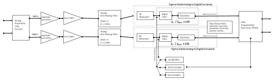
Figure 3: Analog to Digital conversion using Proprietary Dual-ADC technology
Spider systems utilize three sampling frequencies (fin) (16.384 MHz, 20.97152 MHz and 26.2144 MHz) which are used for sampling the analog data by the ADC.
The two analog anti-aliasing filters have cut off frequencies of 1 MHz that should effectively eliminate any frequency components above fin/2, even at the lowest sampling rate of 16.384 MHz which eliminates any data corruption due to aliasing during the analog to digital conversion.
ΔΣ converters employ steep digital filters to down sample the digital data further by several stages. The advantages of using digital filters will be discussed further along the paper. Spiders use a factor of 128 between the input sampling rate at which the ADCs are sampled (fin) to the sampling rate that is desired (fDATA).
This high number of 128 enables Spider products to use a gradual analog anti-aliasing filter which not only eliminates aliasing, but also ensures that the pass band is not affected by ripples or attenuation by the filter and avoids any non-linearity in the phase characteristics and thus preserves the integrity of data. For these specific advantages, ΔΣ ADCs are recommended for Pyroshock data acquisition [1,2].
Digital FIR filters are extremely ideal anti-aliasing or decimation filters in the digital domain. Unlike their analog or IIR counterparts, FIR filters are always stable and can be designed such that there is negligible ripple with linear phase in the pass band while achieving extremely high stop band attenuation. Sharper filters can be achieved just by increasing the order of the filter. With today’s processing power, high orders can be easily achieved as with the case of Texas Instruments’ ΔΣ ADC which is deployed on all the Spider modules.

Figure 4: Digital FIR Filter Response on ΔΣ ADC showing Stop band attenuation over -100 dB to prevent aliasing in the digital domain
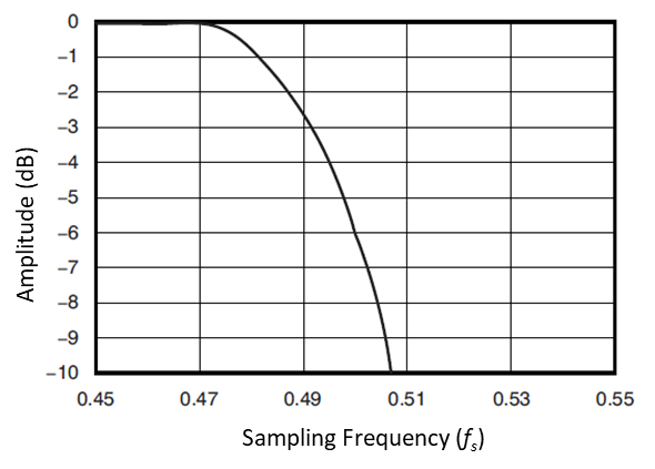
Figure 5: Filter Response of ΔΣ ADC showing negligible pass band attenuation up to 0.47 fs
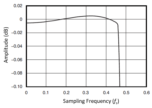
Figure 6: Filter Response of ΔΣ ADC showing negligible Pass band ripple
Figures 4, 5 and 6 displays the filter response of ΔΣ ADC to indicate negligible a pass band ripple and attenuation while achieving extremely high stop band attenuation.
A series of these filters will ensure that the there is no aliasing after conversion into the digital domain and data is also not corrupted due to a pass band ripple or unwanted pass band attenuation.
As it can be seen, the attenuation of frequencies beyond 0.53 fs is over -100 dB. Negligible ripple and pass band attenuation of up to 0.45 fs ensures that data up to 0.45 fs is extremely reliable in making the best choice to ensure data integrity for not only Pyroshock applications, but for any application.
Gibb's Phenomenon
Yet another cause of a ripple appearing in the time domain data is due to the Gibbs phenomenon. This artifact can be observed when there are sharp transients in the along-time data that cannot be effectively represented with the finite number of frequencies available in the digital domain. Other factors that cause this effect include presence of frequencies at the edge of transient band of the digital filters. The sharper the digital filter, the more pronounced is the Gibbs phenomenon.
When the magnitude of these truncated frequencies is small, they do not cause any major changes to the time domain waveform. When the magnitudes are large, which could happen during a Pyroshock test, the Gibbs phenomenon can be present.
One of the simplest methods to observe the Gibbs phenomenon is the feeding of an analyzer with a Square wave input. At the transitions or the discontinuities, the digital data conversion will try to apply up to the highest frequency to represent the discontinuity which causes overshoot and ringing as shown below:

Figure 7: Gibbs Phenomenon on Square wave
The ripples caused by the Gibbs phenomenon are easily eliminated by a special low pass filter called the Ripple Elimination Filter, which is available for most Spider products.
Using this filter will clean out the ripples and eliminate the introduction of artifacts or ripples, especially when Spider systems are used for Pyroshock data acquisition at which such transients are likely.
The filter has a cut off frequency of 0.2 fs with a flat pass band up to 0.1 fs, making it ideal for Pyroshock applications where the desired frequency range is typically 0.1 fs. In addition, the Ripple Elimination Filter introduces attenuation of up to -80dB at 0.45 fs, which thus eliminates any aliased time domain components between 0.45fs and 0.5 fs.
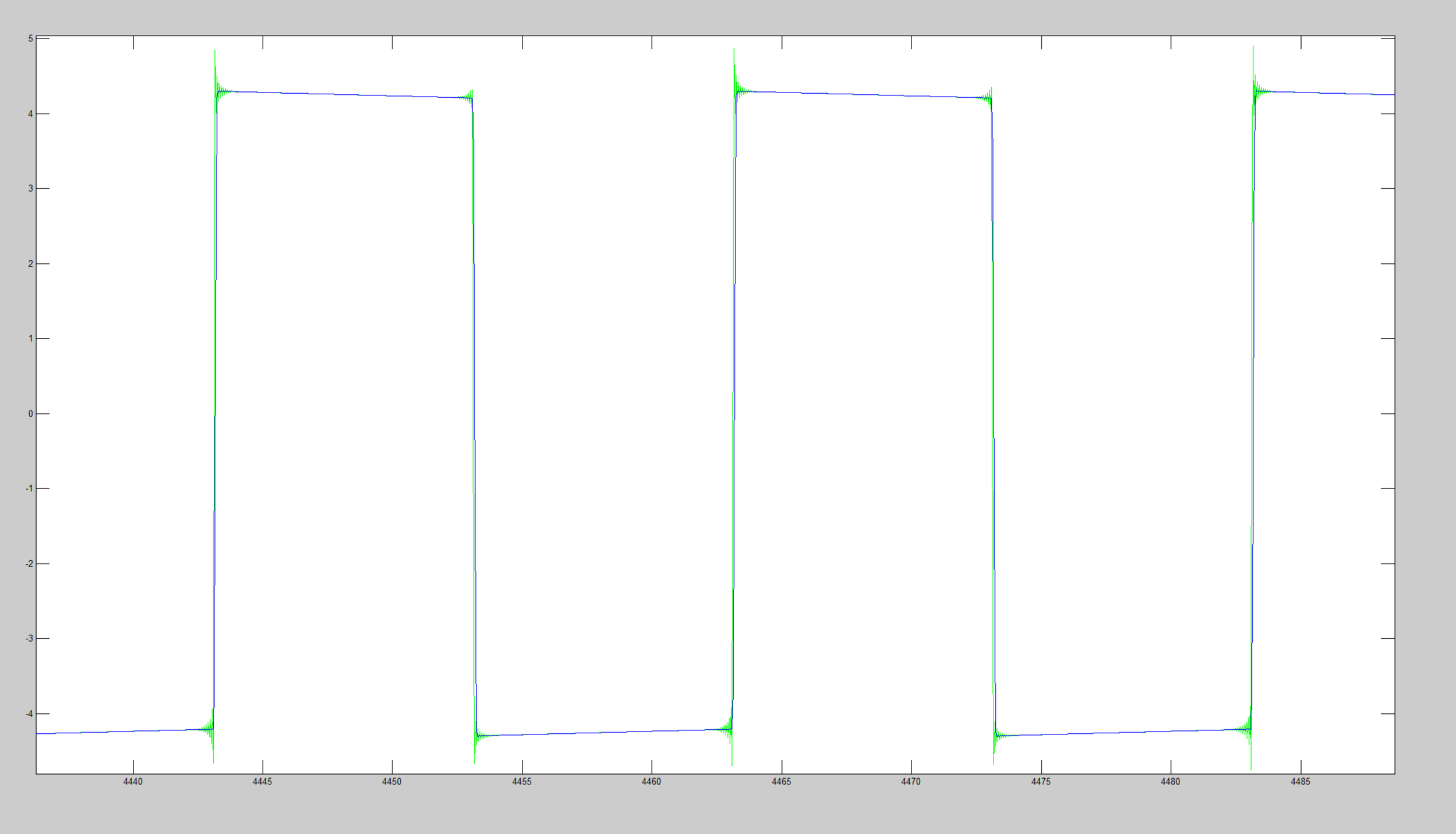
Figure 8: Comparison of data affected by Gibbs Phenomenon (Green) and Clean data using Ripple Elimination Filter (Blue)
Based on the above data, it is easily noticeable that effects of Gibbs phenomenon are possible during Pyroshock tests which alter the time domain data but are easily eliminated using a special filter available on every Spider system. The pass band of up to 0.1 fs is unaffected which makes it an ideal choice for Pyroshock data acquisition.
Additional Filters and Processing on the DSP:
Crystal Instruments' Spider line of products are equipped with a powerful Digital Signal Processor (DSP) which enables Spider systems to run independently without a connection to a PC. With immense power to compute arithmetic calculations, the DSP core of Spider products makes it an ideal choice when extremely high mathematical computations are required.
Decimation could also be performed on the DSP which is also designed to have 127th order FIR filter as a decimation filter. Additional customizable filters at the desired cut-off frequency enables users to customize additional filters with sharp cut-offs to effectively eliminate undesirable frequencies in a narrow band or in a broadband.
With the help of a built-in DSP core, all the processing takes place in real-time to eliminate any requirements for data post processing.
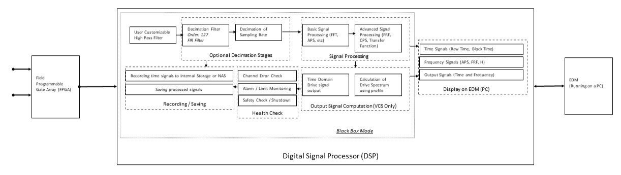
Figure 9: Real-time Signal Processing within the Spider Module
Pyroshock data may at times require specific narrowband or broadband sharp filters to adjust the data and eliminate any undesirable artifacts resulting from the sensors’ resonant frequency or the artifacts caused by data processing itself.
Without any requirements for post-processing at a later time, users can configure custom filters to either remove the high frequencies or the low frequencies while the data is being acquired in real-time.
In addition, DSP also helps in the calculation of velocity data from the accelerometers in real-time, allowing users to view both acceleration and velocity in addition to the filtered and unfiltered data.
Slew Rate Requirements:
It is generally said that the higher slew rate is a superior method to accurately represent the actual data. When the slew rate is lower that what is required, unwanted harmonics are generated which will corrupt the data.
The slew rate of a Sine tone with Amplitude A and frequency f is equal to the maximum slope of the Sine wave (which is the first derivative of the Sine tone at zero crossing) which will be equal to 2πfA.
When the slew rate is far smaller than the required slew rate, the harmonics that can also be present within the pass band can corrupt the data.
For typical Pyroshock applications, the maximum data of interest is at 10 KHz. Considering the highest amplitude levels of up to ±20V at this frequency, the maximum slew rate needed to accurately represent this data would be 2.51 V/µs. Higher slew rates are not very noticeable unless it is required to represent data at higher frequencies.
Extremely high slew rates are less helpful than previously expected [3]. When the Slew rate is many times higher than the maximum slew rate required for the frequencies of interest, it is likely that the amplitudes from undesirable out-of-band frequencies could saturate the input amplifiers of the data acquisition modules.
The slew rates which are slightly higher than the required slew rate are the most ideal since the unwanted frequencies from resonances of sensors are further attenuated, complimenting the analog anti-aliasing filter, and ensuring that the amplifiers are never saturated.
Conclusion:
The combination of a gradual slope analog anti-aliasing filter coupled with 128 times oversampling of the ΔΣ ADC together with the sharp digital FIR filters within the ADC results in aliasing that is easily eliminated while the pass band data is well preserved without any attenuation or ripples. Frequency data up to 0.1 fs is preserved and accurate.
For Pyroshock applications where the time data should be free from any aliased components or any ripples caused by Gibb’s phenomenon, an additional Ripple Elimination Filter is provided. Since the data is sampled by at least 10 times than the required maximum frequency of interest, the additional ripple elimination filter will not cause attenuation to the frequencies in the used pass band.
Users can perform additional processing in real-time using a powerful Digital Signal Processor (DSP) built as the core of the Spiders for any additional processing (including data integration or additional filters) required for Pyroshock applications.
References:
[1] V. I. Bateman, H. Himelblau, and R. Merritt, “Validation of Pyroshock Data,” Sound & Vibration Magazine, 2012.
[2] Bateman, Vesta, “Pyroshock Standards”, Sound and Vibration, vol. 45, pp. 5-6, March 2011.
[3] A. R. Szary, D. R. Firth, "Signal Conditioning Perspectives on Pyroshock Measurement Systems", Sound and Vibration, vol. 47, pp. 7-13, 2013.