
Modal Shaker Testing Using Periodic Random Excitation
Introduction
Modal shaker testing is widely used for experimental modal analysis and to acquire frequency response functions. Either single or multiple modal shakers can be used. The type of excitation used may influence the quality of the testing result and frequency response functions.
Although sinusoidal types of excitation signals are occasionally used for modal shaker testing, these tests are typically performed using broadband random type excitation signals. Among these common excitation types, Pure Random is widely used. The Hanning window is generally applied to alleviate leakage caused by the non-periodic signal.
Another popular excitation type is the Burst Random excitation signal. It gained so much popularity because no window function is required. The requirement is to have the burst length selected so that the response decays enough at the end of each time block data. With this constraint, there will not be any leakage in the measurement and a windowing function is not required.
Two somewhat arbitrary types of excitation signals are Pseudo Random and Periodic Random. The characteristics of these two signal types will be discussed in detail here. The results of using these excitation types will be compared to the more popular Pure Random and Burst Random types. It will be shown that the cost of additional testing time is well worth the superior estimation of MIMO FRF signals.
Background
Before looking into the application of these periodic excitation signal types, the definition of Pseudo Random and Periodic Random are reviewed below.
Pseudo Random is defined as an ergodic, stationary random signal consisting of energy content only at integer multiples of the FFT frequency lines (Δf). The linear spectrum of this signal is shaped to have a constant amplitude, but with random phase. The following figure illustrates the constant amplitude characteristics of the Pseudo Random signal.

Figure 1. Pseudo Random Signal Spectrum
When a sufficient delay time is allowed in the measurement procedure, any transient response to the initiation of the signal will decay, and the resultant input and output blocks are periodic with respect to the sampled period (blocksize).
As for the data processing procedure, for one spectral average the time signal derived from the above frequency spectrum is repeated (Nd + Nc) times. Nd refers to the number of delay blocks; while Nc the number of cyclic blocks, which are captured. The first Nd number of blocks is there to allow the structure to reach periodic response status; no data will be captured for processing; the Nc blocks following are measured and used for cyclic average (time average). This same procedure is repeated for the number of spectral average, after randomizing the phase each time.
The Periodic Random signal is also an ergodic, stationary random signal consisting only of integer multiples of the FFT frequency increment. The frequency spectrum of this signal has random amplitude and random phase distribution. The following figure illustrates the spectrum characteristics.

Figure 2. Periodic Random Signal Spectrum
For each spectral average, the input signal is generated with random amplitude and random phase. The system is excited with the input multiple blocks, until the transient response to the change in excitation signal decays. The input and response histories should then be periodic with respect to the block-size and are saved as one spectra average in the total process. With each new average, a new block of signal, random with respect to previous input signals, is generated so that the resulting measurement will be completely randomized.
During averaging, the same process is used for Pseudo Random, except for each average, not only is the phase randomized, but also the amplitude of the frequency spectrum.
The advantage of averaging the amplitude lies in the fact that possible non-linearities in the structure will not be excited systematically in the same manner for each spectral average as with Pseudo Random. The result is a better ‘linear equivalent’ of the structure obtained at the cost of a much longer testing time.
When using more than one excitation, it is required to obtain enough number of averages with de-correlated sources before calculating the FRF’s. The phase randomization present in both Pseudo and Periodic Random takes care of the necessary de-correlation. It is recommended to use Periodic Random for the MIMO testing.
The number of spectral averages is the number of auto and cross spectra that are averaged together to estimate the FRF measurements. These averages are performed in the frequency domain and are thus referred to as spectral averages. Since the functions averaged are the auto and cross power spectra, the averaging that takes place is a least square averaging procedure that is often referred to as an RMS averaging procedure. The purpose of RMS spectral averages is to eliminate the noise that is random with respect to the averaging procedure in order to reduce the variance on the resulting FRF estimate. This type of averaging does not reduce the effects of bias errors such as leakage. The actual amount of test time contributing to each RMS spectral average is a function of the number of contiguous delay and capture blocks.
Cyclic signal averaging is often used with excitation characteristics in order to better match the time domain input and output signals to the requirements of FFT prior to the application of FFT. Cyclic signal averaging essentially digitally comb filters the time domain data to reduce the amount of information in the data that is not periodic with the observation period (T). This type of averaging reduces the effects of the leakage error.
For either Pseudo Random or Periodic Random types, the same Nd and Nc setting can be selected. For each spectral average, Nd + Nc number of blocks are sent out, and Nc number of blocks of response data on all input channels are measured. The Nd delay blocks are essential to achieve a periodic response of the system before actually starting the collection of data. Without this there would be leakage effects.
The Nc blocks can degenerate to ‘1’ but this means that the non-periodic measurement noise in the observation window will introduce leakage effects. Using Nc different from ‘1’ will (provided they are contiguous) allow us to average out non-periodic components before applying the FFT and thus reduce leakage. Using a window on top of the Nc contiguous time blocks will further reduce leakage effects, but it may not be necessary.
When using more than one source we need to make sure we obtain enough averages with de-correlated sources before calculating the FRF’s and etc. The phase randomization present in both pseudo and periodic random takes care of the necessary de-correlation.
Testing Results
The MIMO testing setup is arranged on an engine block. The engine block is suspended using 4 bungee cords. Two modal shakers are used, as the following photo illustrates the test setup.

Figure 3. Engine Block MIMO Testing Setup
Different excitation types are used to acquire the frequency response functions with the same testing setup parameters. Main testing parameters (i.e., Fspan, Blocksize, Spectral average number) are kept the same with different output types.

Figure 4. White noise excitation
With the White noise excitation type, the Hanning window must be used. This will address the leakage issue from the random excitation signals.

Figure 5. Burst Random excitation
The above figure displays the FRF results with Burst Random excitation, with a burst rate of 50% and no window applied.

Figure 6. Pseudo Random excitation
With Nd=4, and Nc=3, the Pseudo Random excitation is used to run the test. No window is applied either.
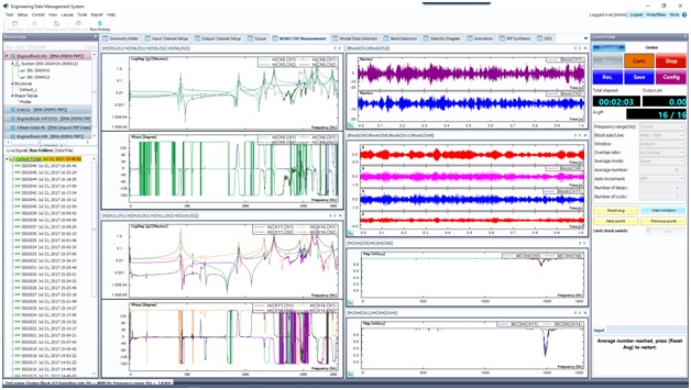
Figure 7. Periodic Random excitation
The above figure displays the results from Periodic Random excitation. It has the same Nd and Nc of Pseudo random.
All excitation types provide fine testing results. Comparing the acquired FRF signals, it is confirmed that Periodic Random does stand out among the excitation types for this Multiple-Input/Multiple-Output test. Multiple coherence signals also prove this result. Despite the cost of additional testing time due to multiple blocks for delay and cyclic average, the improved accuracy of the results is well worth the extra testing time spent.
References
Introduction of a General User Excitation Source Signal for Modal Testing
William A. Fladung, etc., U of Cincinnati