Daily Acoustic Test and Measurement for 7,000 Laptop Fans with Spider System
Laptops are compactly designed computers with a balance between portability and performance. Computing units (such as the CPU, graphic card, wifi chip, etc.) generate heat during operation. When the temperature of the computing units increases, their performance either decreases to guarantee product life or continues working in a high temperature environment which may reduce product life. Therefore, keeping chips in a low temperature state is the best practice to maintain performance and life expectancy.
Laptop fans play a key role in removing excessive heat from laptops and are usually the only moving parts if a DVD/CD ROM drive is not included. The excessively loud sounds generated by fans can annoy some users and the accompanying vibration can damage the motherboard after continuous operation. Either scenario results in user dissatisfaction. In addition, a defective fan can fail without notice and force laptop components to work in an overheated environment. Therefore, it is crucial to quickly and accurately screen out defective products or products that do not meet specifications before the packaging process when hundreds and thousands of laptop fans are manufactured daily on each product line.
A manufacturer of laptop fans was suffering from the results of slow production testing. The testing capacity was limited by testing products with manually operating instruments in a quiet room. Crystal Instruments provided the easy-to-use Spider hardware and EDM software package as a solution to significantly improve their production testing. The package included signal analysis, data acquisition, limit checking, and a digital input/output interface to work with external devices and provide a user-friendly interface for the operator. The test process is streamlined and automated, efficiently testing up to seven thousand fans daily with the Spider system.
User Story
The production tests measure the noise level of each product produced from the production lines. If the autopower spectrum of the noise from a product exceeds the defined limit, the product is considered defective or not qualified.
Two silent boxes are located next to each production line. A silent box isolates a microphone and fan from any external noise. The microphone measures the operating noise of a fan in the box and the Spider computes and compared the autopower spectrum against a pre-set level as the passing criteria. If the fan passes the test, the indication light on the silent box is green. If the test is failed, the light is red.
The testing procedure is described as follows:
The operator scans their ID and computer ID into EDM software.
The operator takes a fan from the production line and scan its ID before placing in a silent box.
Place the fan in a silent box and connect the fan to a power source. The fan should run at operational speed.
Press a button to close the lid of the silent box. When the lid is fully closed, the Spider receives a digital input to start limit checking.
When the measuring time is completed, the Spider generates a digital output to display the result on the indication light and receives a digital input to stop limit checking.
The operator opens the silent box, removes the power source from the fan, and repeats the process from Step 2 for the next item.
One Spider system supports testing for two to four silent boxes.
When a fan requires 17 seconds to test, it takes 33 hours for a silent box to test 7,000 fans.
When a Spider controls two silent boxes, it takes 16.5 hours to test 7,000 fans.

Setup on EDM
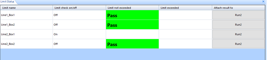
Users connect an external device that sends a high or low voltage signal to the digital input channel of a Spider. The signal enables or disables the limit check on the selected channel. The digital output channel’s status light displays the limit checking results. When a product passes the test, the light is green. When it fails, the light is red. Users can also view results from limit checking on the Limit Status window in EDM.
First, create an FFT analysis test with APS measurement. Configure the input channel table to measure sound pressure from microphones.
Open the Alarm Limits settings and configure limits for desired channels. Limits can be defined for different types of signals from the same channel. Signals include autopower spectrum, time signal, or pk/RMS for the channel.

Enable all four settings located above the Alarm Limit configuration to display and configure the settings for alarm limits.

Users can customize the following properties when a limit is created.
Limit name: name of the limit. One signal can have multiple limits, high limit or low limit. To distinguish multiple limits of the same signal, their names must be different.
As Low/As High: criterion of the limit checking. Limit check fails when the signal is lower than the low limit or higher than the high limit.
Exceeding PCT: provides tolerance to the limit. When the signal exceeds the limit by this given percentage, then the limit check fails.
Event strings: strings that will appear in the run log when the limit is exceeded.
Strings when pass: is displayed in the Limit Status window when the limit has never been exceeded.
Strings when fail: is displayed in the Limit Status window when the limit has been exceeded.
Line width: line width of the limit
Line color: line color of the limit
Limit check on: select a digital input channel and its state to turn on the Limit Check on the signal.
Limit check off: select a digital input channel and its state to turn off the Limit Check on the signal.
Action when exceeded: select a digital output channel to change its state when the limit check is on and the limit is exceeded.

The aforementioned requirements use one input channel and one digital output channel to perform product screening with one silent box.
The following window displays the results from each box. Users can enable or disable limit checking with a digital input for individual signals.