
Choosing a Charge Amplifier for Your Spider: Built-In, Inline, or CA-08A
Part 2 of 2 — Sizing the right hardware for your sensor and measurement range
In Part 1 of this series, we covered why charge mode accelerometers exist, how they're powered, and why the amplifier or converter ( i.e., not the sensor) usually sets the real ceiling on what you can measure. This second part puts that into practice: three ways to size a charge amplifier for a real sensor and a real measurement range, using CI's Spider platform as an example.
Using the Built-In Charge Amplifier on a Spider
Several Spider models include built-in charge amplifiers on their input channels, so a charge sensor can be wired directly into the Spider without any external hardware. Available built-in charge modes include 49000 pC, 10000 pC, 10100 pC, and 1000 pC, and the modes offered vary by Spider model. Check the specification sheet for your unit before assuming a mode is available.
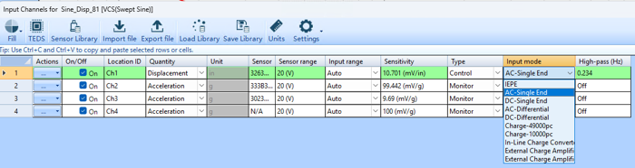
Selecting a charge input mode (Charge-49000pc, Charge-10000pc, etc.) in the Spider input channel configuration.
Each mode name is the charge level, in pC, that the built-in amplifier scales to a 10 V output regardless of the fact that the Spider's overall input range goes up to ±20 V. So a 10000 pC mode means: when the channel receives 10000 pC from the sensor, the built-in amplifier outputs 10 V. Picking the right mode is a matter of matching the sensor's maximum expected charge output to a mode that uses a healthy fraction of that 10 V scale, which provides enough headroom to avoid clipping, but not so little that the signal gets lost in noise. The three examples below walk through a good match, an overloaded match, and an under-scaled match.
Example 1
Sensor: 357B40, 5.0 pC/g sensitivity
Measurement range: ±1000 gpk
Charge mode/range: 10000 pC
Sensor output range = 5 pC/g × 1000 g = ±5000 pC
Voltage to Spider input = 5000 pC ÷ 10000 pC × 10 V = ±5 Vpk
Expected input: 25 g's
5 pC/g × 10 V / 10000 pC = 5 mV/g × 25 g = 125 mV = 0.125 V
The Spider's input range is ±20 V, so ±5 V is within the range. The 10000 pC mode allows this 5 pC/g sensor to measure up to 1000 g.
Example 2
Sensor: 357B40, 5.0 pC/g sensitivity
Measurement range: ±1000 gpk
Charge mode/range: 1000 pC
Sensor output range = 5 pC/g × 1000 g = ±5000 pC
Voltage to Spider input = 5000 pC ÷ 1000 pC × 10 V = ±50 Vpk
Actual measurement range (limited by the 10 V scale of this mode) = 1000 pC ÷ 5 pC/g = ±200 gpk
Expected input: 25 g's
5 pC/g × 10 V / 1000 pC = 50 mV/g × 25 g = 1250 mV = 1.25 V
Here, the sensor's full ±1000 g range would call for ±50 V, far more than the 1000 pC mode's amplifier can output. In practice this channel tops out at ±200 g; anything beyond that clips. The 1000 pC mode is a good choice for this sensor if the actual test input stays under 200 g.
Example 3
Sensor: 357B40, 5.0 pC/g sensitivity
Measurement range: ±1000 gpk
Charge mode: 49000 pC
Sensor output charge range = 5 pC/g × 1000 g = ±5000 pC
Voltage to Spider input = 5000 pC ÷ 49000 pC × 10 V = ±1.02 Vpk
Expected input: 25 g's
5 pC/g × 10 V / 49000 pC = 1.02 mV/g × 25 g = 25.51 mV = 0.02551 V
±1.02 V is well within the Spider's ±20 V range, but it only uses about 10% of the 10 V scale for this mode. The 49000 pC mode isn't a good choice here since the signal is small enough that noise will start to compete with it. It would be a better fit for a much higher-charge-output sensor or a much larger expected g level.
Using an Inline Charge Converter with Charge Sensors
For Spider models that don't include a built-in charge amplifier, an external inline charge converter is the straightforward option. It sits between the sensor and the Spider, takes in a charge signal from the accelerometer, and outputs a proportional voltage signal using one converter per input channel. Because the conversion factor is fixed, the converter has to be chosen with the sensor's expected output already in mind.
Example 1
Sensor: 357B40, 5.0 pC/g sensitivity
Measurement range: ±1000 gpk
Charge converter: 422E36, 10 mV/pC fixed conversion, ±2.5 V output
Converter's charge capacity = ±2.5 V ÷ 10 mV/pC = ±250 pC
Actual measurement range = 250 pC ÷ 5 pC/g = ±50 gpk
Expected input: 25 g's
5 pC/g × 10 mV/pC = 50 mV/g × 25 g = 1250 mV = 1.25 V
The 357B40 is capable of measuring up to 1000 g, but paired with the 422E36 it's effectively capped at ±50 g. The converter's output ceiling, not the sensor, is the limiting factor.
Example 2
Sensor: 357B40, 5.0 pC/g sensitivity
Measurement range: ±1000 gpk
Charge converter: 422E66A, 10 mV/pC fixed conversion, ±5 V output
Actual measurement range = (±5 V ÷ 10 mV/pC) ÷ 5 pC/g = ±100 gpk
Expected input: 25 g's
5 pC/g × 10 mV/pC = 50 mV/g × 25 g = 1250 mV = 1.25 V
Same sensor, same sensitivity, but the higher-output 422E66A doubles the usable range to ±100 g. The lesson in both examples is the same: even with an identical sensor, the converter you pair it with sets the real ceiling on what you can measure.
Using CI's External Charge Amplifier (CA-08A) with Charge Sensors
CI's CA-08A is an eight-channel external charge amplifier built for any instrument that needs a voltage input from a charge mode sensor. It offers low-noise performance across a wide 0.3 Hz to 20 kHz frequency range, with a per-channel selectable sensitivity of 2.3, 23, or 230 mV/pC and a maximum output of ±10 V per channel. This provides far more flexibility than a fixed-ratio inline converter.
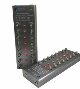
CI CA-08A eight-channel external charge amplifier
Example 1
Sensor: 357B40, 5.0 pC/g sensitivity
Measurement range: ±1000 gpk
CA-08A sensitivity setting: 2.3 mV/pC, ±10 Vpk output
Actual measurement range = (±10 V ÷ 2.3 mV/pC) ÷ 5 pC/g = ±870 gpk
Expected input: 25 g's
5 pC/g × 2.3 mV/pC = 11.5 mV/g × 25 g = 287.5 mV = 0.2875 V
Expected input: 2.5 g's
5 pC/g × 2.3 mV/pC = 11.5 mV/g × 2.5 g = 28.75 mV = 0.02875 V
At the 2.3 mV/pC setting, the CA-08A lets this 1000 g-capable sensor use nearly all of its range, up to ±870 g. This setting is suitable for measuring large vibrations.
Example 2
Sensor: 357B40, 5.0 pC/g sensitivity
Measurement range: ±1000 gpk
CA-08A sensitivity setting: 230 mV/pC, ±10 Vpk output
Actual measurement range = (±10 V ÷ 230 mV/pC) ÷ 5 pC/g = ±8.7 gpk
Expected input: 2.5 g's
5 pC/g × 230 mV/pC = 1150 mV/g × 2.5 g = 2875 mV = 2.875 V
Switching to the 230 mV/pC setting shrinks the usable range to just ±8.7 g, which is useful if you're measuring small vibrations and want maximum resolution, but a reminder that the CA-08A's selectable gain is a tool for tuning resolution against range, not just a way to “boost” the signal.
Choosing the Right Path for Your Setup
All three approaches (i.e., a Spider's built-in charge amplifier, an external inline charge converter, or CI's CA-08A) perform the same fundamental job: turn a charge sensor's high-impedance output into a voltage a data acquisition system can read. Which one makes sense comes down to your hardware and how much flexibility you need:
If your Spider model has a built-in charge mode that comfortably matches your sensor's expected output, it's the simplest option because it requires no extra hardware, no extra cabling.
If your Spider doesn't support charge input directly, an inline converter is compact and inexpensive, but its fixed gain means you need to know your expected signal range before you buy one.
If you need adjustable sensitivity, multiple channels, or the ability to fine-tune resolution against measurement range on the fly, the CA-08A's selectable gain settings give you that flexibility in a single unit.
In every case, the same rule of thumb applies: pick a mode or setting that uses a healthy portion of the amplifier's voltage range for your expected signal. Provide enough headroom to avoid clipping on peaks, but not so much unused range that noise starts to dominate the measurement.