
Mode Shape Characterization
Shaker applications involve the use of many attachments to the shaker’s armature. Head expanders, fixtures, adapters, and devices under test (DUT’s), all attach to the shaker for the testing process. While it is common to simply consider the added mass of these components, their deformation during vibration can also have a significant impact on the vibrations experienced at any certain point of interest.
The deformation mentioned above is most prevalent in association with the natural frequencies, or resonances, of an object. The shape of the deformation at these instances is called a “mode shape” and is the basis for the discussion of this article.
In this opportunity, we used the Crystal Instruments Spider-80X in conjunction with a Sentek Dynamics M3240A shaker to excite and characterize the mode shapes of a steel plate measuring 24” x 24” x 3/16”. The test setup can be viewed in Figure 1 below.

Figure 1: Sentek Dynamics Shaker and Steel Plate Setup
For this experiment, a linear sine sweep was run on an M3240A Sentek Dynamics shaker from 5 to 2000Hz at a sweep rate of 1Hz/sec. The acceleration levels were increased in a staggered manner to allow for quicker resolution of patterns at higher frequencies where displacement becomes very small. The full profile can be seen below in Figure 2.

Figure 2: Sine Sweep Profile
A 100mV/G IEPE accelerometer was attached to the armature below our steel plate as a control reference and salt was occasionally scattered across the plate to highlight the patterns formed by the mode shapes. The lines created where the salt gathers indicate the areas of least displacement and acceleration, while the salt is cleared away from the areas with highest displacement and acceleration. Figure 3 shows the results of this run, and Figure 4 shows the patterns formed at several resonating frequencies.
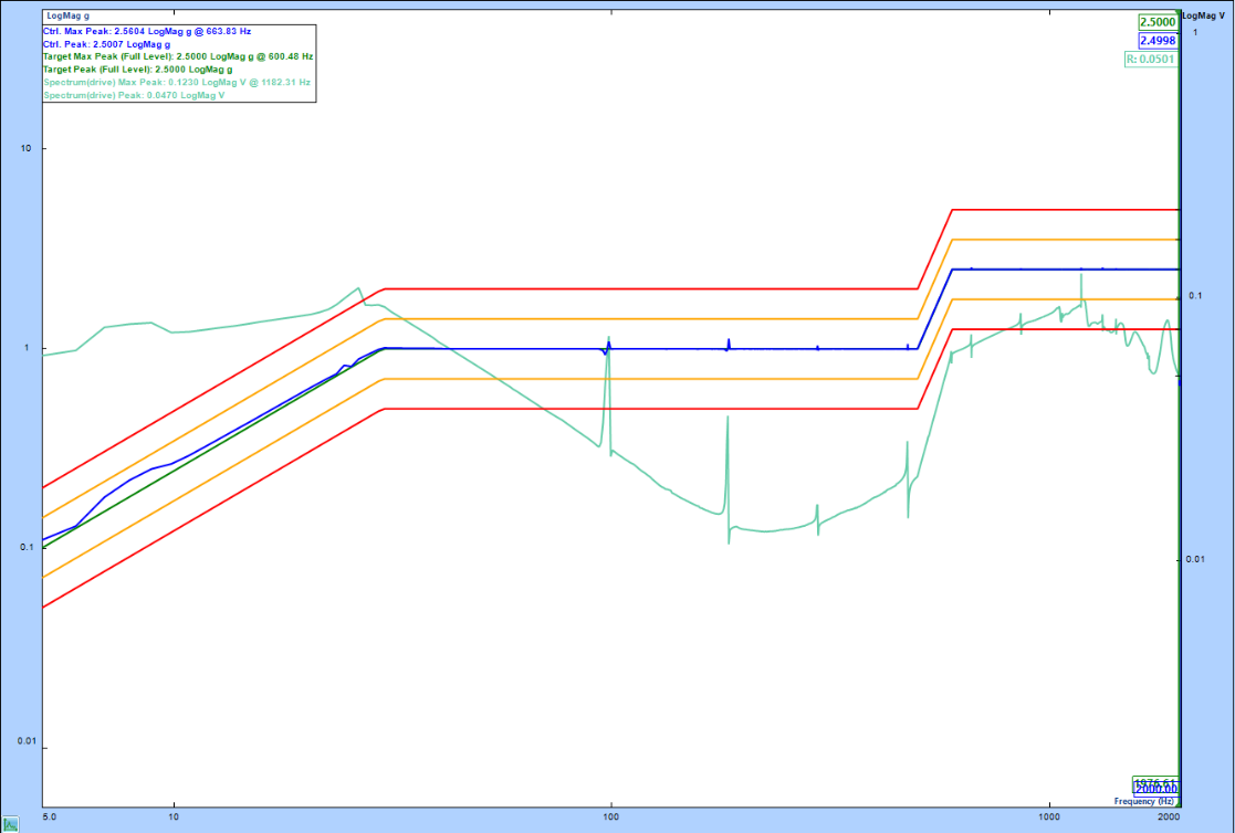
Figure 3: Sine Sweep Profile Results
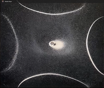

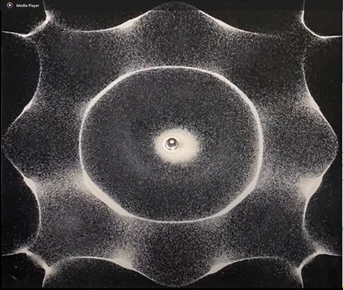
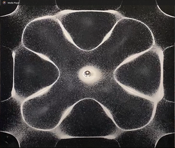

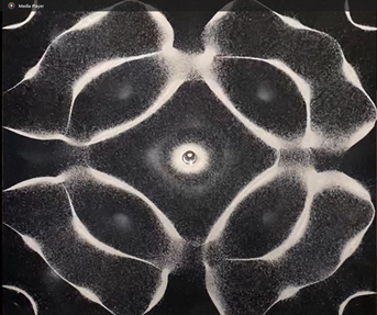
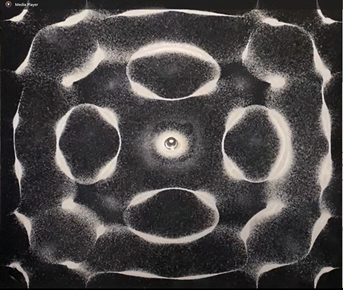
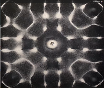
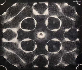
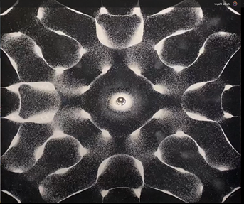
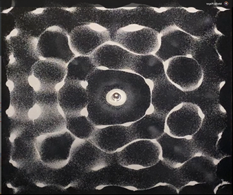
Figure 4: Mode Shape Patterns (5-2000 Hz)
From these results we can conclude that the monitored area of a device under test has a significant impact on the forces and movement seen when taken across a spectrum that includes resonant frequencies. The location of the control accelerometer can have a dramatic impact on the test during these times due to the varying acceleration in different regions of the device under test. This demonstrates the importance of these considerations when designing a device for shaker testing and leads to questions of how best to consider these factors when designing a test or system. We will continue this line of thinking in future articles showing how modal analysis, finite element analysis, and device characterization can all be used to address these circumstances and produce better test results.
Sentek Dynamics is a leader in the vibration testing industry working in conjunction with Crystal Instruments to develop methods and technology to deliver the best testing results possible with the highest safety factors to customers seeking complete solutions for their vibration testing needs. We anticipate and pursue growth through continuous experimentation and improvement, both within the Sentek Dynamics team and in conjunction with customers who wish to push the boundaries of their vibration testing applications.
Contact Sentek Dynamics to learn more about our turn-key vibration testing solutions. For testing inquiries or to schedule a product demo day contact Sentek Dynamics at https://www.sentekdynamics.com/testing-evaluation-services.
For inquiries about vibration controllers and data-acquisition systems, contact Crystal Instruments at https://www.crystalinstruments.com/contact-us.