
A History of Vibration Test Controllers
Download PDF | © Copyright Crystal Instruments 2016, All Rights Reserved.
Authors: James Zhuge, Ph.D. - Crystal Instruments, Santa Clara, CA | Dave Formenti, Santa Cruz, CA | Mark Richardson, Vibrant Technology, Inc., Scotts Valley, CA
This article discusses four generations of digital vibration exciter control systems developed by U.S. companies over a period of 40 years. The controllers are categorized as standalone, PC-based, PC-tethered, and fully networked.
The age of modern vibration controllers dawned in the mid 1970s with the maturity of the minicomputer and adoption of the fast-Fourier transform and related signal processing mathematics for practical vibration testing. Technical advancements borrowed from other fields gave rapid rise to a new class of digital closed-loop controllers. While commercial vibration test controllers existed previously, none of them was capable of running multiple types of tests such as sine, random and shock. The minicomputer and the personal computer which soon eclipsed it, provided a new level of flexibility in a tightly integrated testing system. This new architecture also provided superior control and a host of other benefits leading to better presentation, retention and communication of test results. The past 30-35 years clearly mark the golden era of rapid development in this field. We restrict our attention here to the most significant vibration control products of the years 1970 to 2010. This in no way suggests disrespect for some of the unique dedicated instruments that came before. Prior to this period, landmark work in swept-sine control was performed at Spectral Dynamics, Bruel & Kjar and Solartron, with each company creating its own sophisticated commercial instrument solutions. In addition, MB Electronics is credited with developing the earliest random vibration controllers using analog filter banks. Much of the theory underlying today’s random control system designs can be traced back to the early work of Theron Usher at Yale University and at MB.
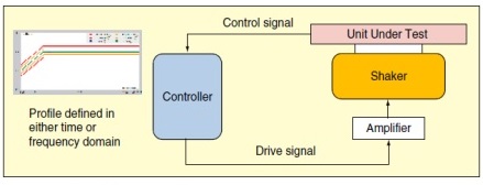
Figure 1. Closed-loop control process.
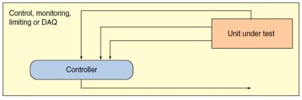
Figure 2. Unit under test with multiple control channels.
Vibration Control System
The digital vibration control system (VCS) is a computer system that can conduct closed-loop control of vibration testing systems. It generates an electronic signal that drives an external amplifier, which then provides the drive signal to either a hydraulic or electrodynamic (ED) shaker or an acoustic driver. The response of the unit under test (UUT) is measured by the VCS and used as a feedback control signal. The response is usually measured with one or more accelerometers. In the closed-loop control environment, the control signal must follow certain prespecified characteristics in either the time or frequency domain. These characteristics have been defined for sine, random, sine-on-random, random-on-random, classical shock, shock response spectrum (SRS), road simulation and other forms of control.
Most tests use a single shaker to excite one axis of the structure. More sophisticated tests use multiple shakers or acoustic drivers to excite the structure at multiple points and/or in multiple directions simultaneously. When multiple exciters are used, the control system will involve MIMO (Multiple-Input/Multiple-Output) cross channel calculations. Single-axis control dominates the industry today, so it is emphasized in this article.
The control signal refers to one or multiple signals measured from the UUT. If the control signal does not contain the desired (time or frequency) testing profile, adjustments are made to the drive signal until the control signal converges to the desired profile. The control system continuously corrects the drive signal, taking into account the dynamics of the shaker and UUT to maintain accurate control. Safety checking is enhanced by using a distributed-processing architecture that is independent of the host computer.
Figure 1 shows the closed-loop control process. Sensors such as accelerometers are commonly used to measure the response of the UUT and provide the feedback control signal. A random controller will continuously output a random drive signal so that the power spectral density of the control signal converges on a predefined target or reference spectrum. The target or reference spectrum is also called a profile spectrum. A sine controller will continuously output a swept sine signal at a certain voltage so that the control signal, which is also a sine-like signal, will follow the predefined amplitude spectrum while sweeping the frequency at a rate programmed into the controller. Classical shock controllers use a predefined time history as the target profile. Shock response spectrum (SRS) control uses a predefined SRS spectrum. A road simulation controller uses a very long predefined time signal as the target profile. Sine-on-random and random-on-random control are also called mixed-mode controls. Each combines random control with another mode of control, so their test setup is more complex. A single controller simultaneously causes each component to adhere to its target profile.
Nearly all of the commercial controllers on the market today provide random and sine control. Roughly half of them also contain classical shock control. Mixed mode, SRS, transient history and road simulation are less common, and are typically used for specialized applications.
Even with one excitation source, there are good reasons to measure the response at many points on the UUT. With multiple control channels as shown in Figure 2, the user can use different control strategies, such as the minimum, maximum or average response. For example, an average response strategy might average together multiple control signals in the frequency domain with a different weighting factor for each channel. A typical VCS strategy might also monitor critical response points or parameters of the UUT.
Innovators – First-Generation VCS
One of the earliest digital VCSs was developed by Hewlett Packard in the mid 1970s. HP researched many different closed-loop control algorithms and implemented them one on of the earliest FFT-based signal analyzer systems, the HP5451 shown in Figure 3. The HP5451 analyzer was based on an HP2100 series minicom-puter, which had very limited memory and computational resources. HP engineers had to use various clever signal processing methods to overcome these computational limitations, and provide a few kHz of real-time bandwidth for effective closed-loop control. Two engineers (Ron Potter and Peter Moseley) made many of the earliest contributions to these early generation controllers.
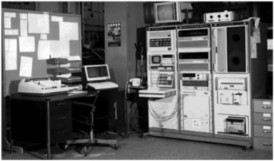
Figure 3. HP5451 dynamic analysis system.

Figure 4. HP5427 vibration control system.
After HP successfully tested the control algorithms with the HP5451, a dedicated VCS (HP5427) was commercially produced in the late 1970s. It used the same computer architecture as the HP5451 but was packaged in a single bay of hardware as shown in Figure 4 and was dedicated to vibration control alone.
Time Data Corp, which became a division of the General Radio Company (later called GenRad), was also an early developer of VCS products. In the early 1970s, two engineers at Time Data, Edwin Sloane and Charles Heizman, were granted a patent for random vibration control. It was based on the PDP-11 computer made by Digital Equipment Company (DEC) (see Figure 5). The Gen-Rad GR2500 series standalone control system was probably the most successful controller sold during the 1980s (see Figure 6).
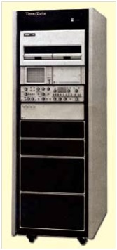
Figure 5. GenRad Time/Data TDV 20 vibration control system.
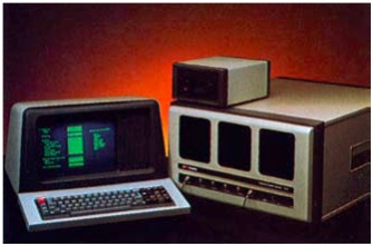
Figure 6. GenRad 2511 vibration control system.
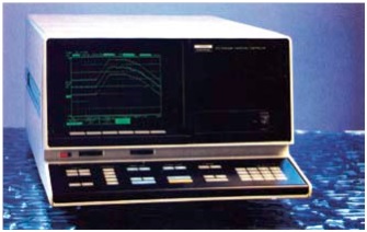
Figure 7. Solartron 1210 vibration control system.
The vibration control group at the Structural Test Products (STP) Division of GenRad was later sold to the Spectral Dynamics Corporation. Marcos Underwood, chief engineer for the GenRad controller, focused more on “error” control instead of on the proportional control used by HP. Another Spectral Dynamics engineer, Tony Keller, also made many contributions to controller development in those early days.
Beginning in the 1980s, Leuven Measurement Systems (LMS), a Belgian company, worked with HP to provide vibration control software for HP’s new Paragon FFT analyzer hardware. LMS’s relationship as a software supplier for HP systems was similar to Microsoft’s relationship with IBM and the PC. Like Microsoft, LMS developed and sold only software that ran on the HP hardware platform.
Other players of earlier generation VCSs were Ling Electronics, MB Dynamics, and Solartron (see Figure 7). First-generation VCSs sold in the range of $80,000 to $200,000 but were still overly sophisticated and difficult to use. Nevertheless, most of the control algorithms in use today were developed during the 1970s and early 1980s. In addition, the U.S. military-driven MIL-STD-810 testing standard, which sets the most comprehensive procedure for environmental testing, was established in this period.
One of the earliest digital VCSs was developed by Hewlett Packard in the mid 1970s. HP researched many different closed-loop control algorithms and implemented them one on of the earliest FFT-based signal analyzer systems, the HP5451 shown in Figure 3. The HP5451 analyzer was based on an HP2100 series minicom-puter, which had very limited memory and computational resources. HP engineers had to use various clever signal processing methods to overcome these computational limitations, and provide a few kHz of real-time bandwidth for effective closed-loop control. Two engineers (Ron Potter and Peter Moseley) made many of the earliest contributions to these early generation controllers.
After HP successfully tested the control algorithms with the HP5451, a dedicated VCS (HP5427) was commercially produced in the late 1970s. It used the same computer architecture as the HP5451 but was packaged in a single bay of hardware as shown in Figure 4 and was dedicated to vibration control alone.
Time Data Corp, which became a division of the General Radio Company (later called GenRad), was also an early developer of VCS products. In the early 1970s, two engineers at Time Data, Edwin Sloane and Charles Heizman, were granted a patent for random vibration control. It was based on the PDP-11 computer made by Digital Equipment Company (DEC) (see Figure 5). The Gen-Rad GR2500 series standalone control system was probably the most successful controller sold during the 1980s (see Figure 6).
The vibration control group at the Structural Test Products (STP) Division of GenRad was later sold to the Spectral Dynamics Corporation. Marcos Underwood, chief engineer for the GenRad controller, focused more on “error” control instead of on the proportional control used by HP. Another Spectral Dynamics engineer, Tony Keller, also made many contributions to controller development in those early days.
Beginning in the 1980s, Leuven Measurement Systems (LMS), a Belgian company, worked with HP to provide vibration control software for HP’s new Paragon FFT analyzer hardware. LMS’s relationship as a software supplier for HP systems was similar to Microsoft’s relationship with IBM and the PC. Like Microsoft, LMS developed and sold only software that ran on the HP hardware platform.
Other players of earlier generation VCSs were Ling Electronics, MB Dynamics, and Solartron (see Figure 7). First-generation VCSs sold in the range of $80,000 to $200,000 but were still overly sophisticated and difficult to use. Nevertheless, most of the control algorithms in use today were developed during the 1970s and early 1980s. In addition, the U.S. military-driven MIL-STD-810 testing standard, which sets the most comprehensive procedure for environmental testing, was established in this period.
Second-Generation PC-Based VCS
During the 1980s, the IBM-PC and its clones began to gain popularity for industrial applications. Many companies started to use the PC as the platform for data acquisition and dynamic signal analysis. One of the first PC-based VCSs was the DP540, developed by Data Physics, a company founded by Sri Welaratna and Dave Snyder, two former HP engineers (see Figure 8). This early DOS-based controller had an impressive and flexible graphical user interface for that era. The DP540 used multiple ISA plug-in DSP cards for inputting control signals to the PC and outputting the drive signal. Each card had several digital signal processing chips (DSPs) and analog-to-digital (A/D) or digital-to-analog (D/A) converter circuits. James Zhuge was a key member of the Data Physics development team at that time. This product was very successful during the 1990s. The Lansmont Corp. also initiated a developmental program in collaboration with Data Physics and resulted in the Lansmont TTVI controller.
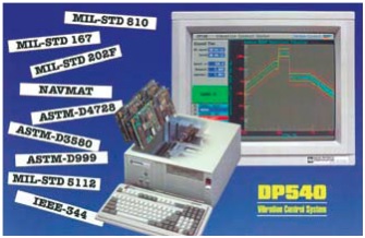
Figure 8. Data Physics DP540 vibration control system.
In the same time frame as the DP540 (and later the Windows based DP550) several other vendors released PC-based VCSs. They including: Puma from Spectral Dynamics, DVC from UniDyn, and VWin from Unholtz-Dickie. All of these second-generation PC-based VCSs took advantage of the low price and graphics capabilities of the PC with the signal processing power of dedicated DSPs. The usability and closed-loop performance of these products was greatly enhanced over their predecessors. The continuous drop in price of the VCS throughout the 1990s made it more affordable for commercial applications such as electronics and packaging testing, and the market size for VCS continually increased year by year.
A shortcoming of second-generation VCSs, however, was that they were heavily dependent on the performance of the PC. This was because the closed-loop control relied on the processing power of the plug-in cards, the power of the CPU in the PC, and the communications between the two. Many of these systems used the ISA bus, which restricted the loop time of the controller due to interrupts, bus traffic, and the bus bandwidth of the PC. Even when a PCI bus was used, the PC CPU still played a significant role in the control process. Moreover, the performance of the plug-in cards was limited due to electrical interference from the PC.
LMS and another company, m+p Corporation, continued to build software-only VCS solutions using the HP Paragon and newer VXI hardware, with their software running on computers in the UNIX operating system. These systems were mainly targeted at high-end applications where simultaneous data acquisition was also a requirement during a test.
Third-Generation VCS – PC Tethered
In 1996, a new company Dactron Inc., founded by Joseph Driscoll (former Lansmont CEO) and James Zhuge, pursued development of a next-generation VCS. They recognized several shortcomings in the existing technology and identified opportunities for improvement. The Dactron LASER series was the result of this development. The PC was not used in the control loop, but only as a “peripheral” of the VCS.
Using this strategy, a much faster loop time could be achieved. Many new algorithms were realized in this controller implementation, which took advantage of floating-point DSP chips. Justin Tang, the hardware manager at Dactron, designed the controller hardware, and George Ma, senior software engineer, designed the Windows-based user interface software.
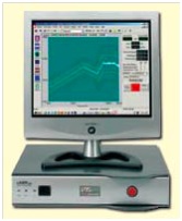
Figure 9. LDS-Dactron LASER
vibration control system.
The LASER, shown in Figure 9, was the first VCS product that used multiple-floating-point DSP processors, 24-bit delta/sigma A/D converters and the PCI and USB bus technology. The original software was based on the native Microsoft MFC. This new signal processing technology and architecture allowed the system to perform many more functions while still maintaining its ease-of-use.
In 2001 Dactron was acquired by LDS (Ling Dynamic Systems), the world’s largest ED shaker manufacturer at that time. LDS has subsequently been merged with Bruel & Kjar (B&K), a leading noise and vibration equipment vendor. Other companies including Vibration Research (VR) and DP introduced third-generation VCSs using this same architecture with the control loop independent of the PC. Data Physics introduced the Abacus system, a high-channel VCS constructed from a number of Intel Pentium-based boxes. Each box or module can have up to 32 input channels, and multiple modules can be connected together through Ethernet and a proprietary synchronization cable.
Both the VRC VR 8500/9500 series and the DP Abacus are important steps toward a fourth-generation VCS, since they both use high-speed Ethernet connectivity. However both require an extra proprietary synchronization cable and still rely on a PC for their operation.
Fourth-Generation VCS – Synchronously Networked
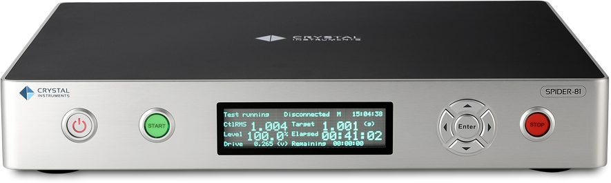
In 2010 Crystal Instruments, founded by James Zhuge, announced the release of Spider-81, the next generation of vibration control systems. Spider-81 is the first network-based vibration control system that integrates the IEEE 1588 time synchronization technology into its design. The control modules can be configured with as little as four to as many as 1024 response channels. This design has established a new standard in reliability, measurement accuracy, and control loop performance. Spider-81 is also equipped with multiple-drive output channels, internal backup battery, and uses an Ethernet connection to the PC.
Spider-81 is considered a fourth-generation controller in that it uses the IEEE 1588 Ethernet-based time synchronization technology that allows the controller to be physically located far from the host PC. This distributed design structure greatly reduces noise and electrical interference. One PC can be used to monitor multiple controllers over a network. With a wireless network router, the PC can monitor its controllers via Wi-Fi if desired.
The IEEE 1588 time synchronization technology permits controllers on the same network to be synchronized within 100-ns accuracy, which guarantees ±1° cross-channel phase match up to 20 kHz. No synchronization cable is required. With this unique distributed technology and high-speed Ethernet interface, the networked components truly act as one integrated system.
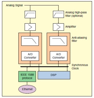
Figure 10. Input front-ends in one hardware module.
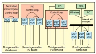
Figure 11. Architecture of four generations of vibration control systems.
How Does IEEE 1588 Work?
The IEEE 1588 protocol is designed to synchronize separate clocks in different modules within the same network (see Figure 10). The method can be summarized as follows: First, the most accurate clock is selected (using a best-master-clock algorithm) to establish a master clock. The other clocks then become slave clocks. The IEEE 1588 protocol synchronizes each slave clock to the master clock to synchronize the entire system.
There are two unknowns that must be calculated in the IEEE 1588 protocol to synchronize two clocks: the time offset between the two clocks and the message transmission delay from one clock to another. The master clock first sends a time-stamped message to a slave clock. The difference between the master clock time on the message and the slave clock time is equivalent to the sum of the offset and transmission delay.
The slave clock then adjusts its clock to match the time-stamped message. The difference between the times of the two clocks is now equal to only the message transmission delay time. The slave follows up with a time-stamped message to the master clock, which replies with another time-stamped message. The slave clock, using the time delay before it received the master’s reply, can calculate the overall time delay for both directions. It averages the two delays and adjusts its clock to match the master clock. More details about the IEEE 1588 standard are given in References 1 and 2. Once the clocks on all network devices are synchronized using IEEE 1588, the sampling clocks of the A/D and D/A converters in each module can then be easily synchronized.
Comparing Architectures of the Four Generations
A comparison of the architecture of four generations of VCSs is shown in Figure 11.
Role of PC. The first-generation controllers were based on minicomputers where all of the closed-loop control and user interfaces were performed in one computer. In the second generation, the PC replaced the minicomputer, but it was still part of the control loop. Since data were transferred through the PC bus, any disturbance in the PC performance had a direct impact on the control loop performance. In the third generation, the PC was more isolated from the control loop, basically serving as the operator’s interface to the control process. In the fourth generation, high-speed communication and accurate time synchronization all happen on the LAN (Local Area Network). The PC becomes one of the operator interfaces residing on the LAN. The user has the choice of accessing a controller through a PC, wireless interface, handheld pendant, PDA (Personal Digital Assistant) or other means. While some earlier generations did have network capability, they were not originally designed as high-speed network devices and suffered from the lack of submicrosecond time synchronization.
A fully networked controller provides significant advantages over previous generations. The controller can be placed close to the shaker table and operated either near to the shaker or from a control room a few hundred meters away. A PC can be used to configure the test setup or act as an operator interface. During a test, the controller can also be accessed using other devices such as a dedicated pendant or PDA.
Real-Time Performance. First-generation VCSs were not truly real-time systems. Real time requires that every data point of the control signals is used for creating the next drive signal. To calculate the system transfer function, the minicomputer usually had to skip over input data frames. Therefore, it could take several seconds to complete the loop time.
Second-generation VCSs were real-time systems. All input samples were used to compute the drive signals, and the loop time could be as short as a fraction of second. Taking advantage of the PC, the user interface was greatly improved, and production costs fell.
Third-generation VCSs can be called “over real time,” since these systems have the capability of using the same input data for multiple tasks. For example, in the Dactron Random controller, multiple control loops could be running for different frequency bands simultaneously. In an extreme case of sine-on-random control, two random-control kernels, plus 12 sine-control kernels, could all run simultaneously. The control loop time can be as short as a few milliseconds.
The mechanical characteristics of the UUT and the dynamic range of the response signals both have a significant influence on closed-loop control performance. The first and second-generation controllers were unable to meet some demanding applications, where a 5 kHz real-time control bandwidth and up to 70 dB control dynamic range were required. The situation changed when third-generation VCSs were introduced. Thanks to the use of floating-point processors and the sigma-delta converters, the realtime bandwidth and the dynamic range of the control system far exceeded the external mechanical requirements for the test and the dynamic range of the transducers. From then on, improving the bandwidth and control dynamic range of the VCS did not provide any real benefits to the customer.
Algorithm Improvement. With better electronics and faster processors, various software algorithms were included in the later generations of the controllers. Here are a few examples:
In the Dactron controller, a sophisticated filtering technique was developed so that the random controller could have much higher frequency resolution in the low-frequency end. This is called multi-resolution control.
The VR controller incorporated Kurtosis control so that the random control signal could be made non-Gaussian to more closely simulate measured environments recorded from the road and elsewhere.
With the Spectral Dynamics controller, a better filter shape was implemented in the sine controller. It provides better filter pass band characteristics compared with those using rectangular windows during spectral analysis.
Spider-81 Vibration Controller
Spider-81 is the first network-based vibration control system that integrates the IEEE 1588 time synchronization technology into its design. The base module can be configured with four or eight response channels but can be expanded up to very high channel counts. This VCS design features very high reliability, high measurement accuracy, high control loop performance and ease of use. Spider-81 is equipped with multiple drive output channels, bright LCD, digital I/O interface, internal backup battery and a RUN/Stop button. Spider-81 uses an Ethernet connection.
Spider-81 is considered a fourth-generation of controller because of the following new features:
DSP Centralized Architecture. Spider-81 is the first controller that directly integrates time-synchronized Ethernet connectivity with embedded DSP technology. This strategy greatly increases the control loop performance, system reliability and failure protection. It also allows a large number of channels to be configured without sacrificing system performance.
Simple Network Connection. Ethernet connectivity allows the Spider-81 to be physically located far from the host PC. This distributed structure greatly reduces noise and electrical interference. One PC can monitor and control multiple controllers over a network. Since all the control processing and data recording are executed locally inside the controller, the network connection won’t affect the control reliability. With wireless network routers, the PC can easily connect to the Spider remotely via Wi-Fi if desired.
Time Synchronization between Multiple Modules. The Spider-81 is built on IEEE 1588 time synchronization technology. Spider modules on the same network can be synchronized with up to 100 nsec accuracy, which guarantees ±1° cross-channel phase matchup to 20 kHz. With this unique technology and high-speed Ethernet data transfer, the distributed components on the network truly act as one integrated system.
Black-Box Mode – Run without PC. The Spider-81 can be executed in black box mode, which allows it to operate without a PC attached. In this mode, a PC is used only to configure the control system before it starts operation and to download data after the test is complete. During the test, the controller can be operated according to a preset schedule or from a variety of external devices, such a control pendant, a Wi-Fi enabled PDA, or an iPad.
On-Board LCD Display. Each SPIDER-81 is equipped with a bright front-panel LCD that displays system status and test information. Real-time status such as control RMS or sweeping frequency can be instantly viewed.
Designed for High Reliability. Spider-81 is the first VCS designed for fail-safe operation even in the event of a network or power loss. A backup battery allows the controller to continue to function and save status information if it loses power. Advanced safety routines allow sensor failures to be detected within milliseconds.
Designed for High Accuracy. Using a patented technology, Spider-81 is the first VCS that achieves 130-dB input dynamic range. Each measurement channel can detect signals as small as 6 μV and as large as 20 V. This completely eliminates the need for input range or gain settings.
Designed for High Control Performance. By using enhanced control algorithms and a simplified DSP architecture, the feedback loop time of sine and random control are all greatly reduced. A reduced control loop time provides improved capability for resonance search and for dwell or control at high Q resonances. Its higher performance also provides better safety protection.
Integrated with Dynamic Signal Analysis. Spider-81 is integrated with general signal analysis functions including time-stream recording, transient capture, FFT, auto-power spectra, and transfer function analysis. Multiple Spider-80 DSA modules can work together with a Spider-81 VCS module as one integrated system. Spider-81 is enabled with long waveform recording functions. For mission critical testing, each input channel can acquire time domain data and store the signals into the flash memory onboard.
References
IEEE Std 1588-2008, “IEEE Standard for a Precision Clock Synchronization Protocol for Networked Measurement and Control Systems,” July 2008.
J. C. Edison, “The Application of IEEE 1588 to Test and Measurement Systems,” Agilent Laboratories, January 2005.