
Charge Mode Accelerometers: IEPE vs. Charge, Powering, and Measurement Range
Part 1 of 2 — The fundamentals behind charge mode measurement
Introduction
Anyone who's tried to run vibration testing in a genuinely hot environment such as an exhaust manifold, a turbine test cell, or an environmental chamber will eventually run into the same wall: the accelerometer that works everywhere else stops working there. Most accelerometers in use today are IEPE sensors, which build a small signal-conditioning amplifier right into the sensor housing. That's convenient, but that same amplifier is also the sensor's weak point at temperature: standard IEPE electronics peak at around 248°F (120°C), and even with specialized high-temperature components, that ceiling only stretches to about 329°F (165°C). It's a problem Crystal Instruments' Spider systems are built to handle from the ground up, as this series will get into.
Charge mode accelerometers sidestep that ceiling by leaving the amplifier out of the sensor entirely. With no onboard electronics to protect, a charge sensor's high-temperature limit is set only by the Curie temperature of its piezoelectric material. This is the point at which the crystal itself stops behaving piezoelectrically. That headroom is substantial: charge sensors are commonly rated from around –95°F up to 1000°F (–71°C to 538°C), and specialized designs push even higher. It's exactly why charge sensors remain the standard choice anywhere a test article gets seriously hot, long after IEPE became the default everywhere else.
The tradeoff shows up downstream, not at the sensor. A charge signal is inherently high-impedance, which makes it far more prone to picking up electrical noise and electromagnetic interference than the low-impedance voltage an IEPE sensor outputs. Even flexing or vibrating the cable itself can generate noise. The result is a phenomenon called triboelectric noise, caused by two dissimilar materials rubbing together inside the cable jacket. As a result, charge measurements call for specially treated, low-noise cable, and cable length has to be calculated carefully to avoid losing high-frequency content. Getting a usable measurement takes a little more care on the front-end, and the right piece of equipment to turn that fragile, very-low-capacitance charge signal into a voltage a data acquisition system can actually read. That conversion is what the rest of this two-part series covers: what it does, and how to size it correctly.
Crystal Instruments designed its Spider systems around exactly this range of sensor types. Every Spider platform from the standalone Spider-81, Spider-81B, and Spider-80X units to the high-channel-count Spider-80Xi and Spider-80M platforms accept Charge, IEPE, and voltage inputs. Several front-end types add strain gage, RTD, and thermocouple support on top of that. The voltage input alone covers four modes: AC-single end, DC-single end, AC-differential, and DC-differential. This range allows a channel to accept a signal from an external signal conditioner when a test calls for one. IEPE channels supply their own constant-current excitation, so a separate IEPE power source isn't needed either.
Charge input is where this really pays off. Fitting a charge amplifier into a compact, multi-mode data acquisition front end and a vibration controller is a tight design problem. Isolation, noise performance, and channel density all compete for the same board space, and Crystal Instruments was one of the first to solve this issue. The payoff for the user is straightforward: one less external box to buy, cable, calibrate, and maintain, and one less point of failure in the signal chain. It also removes a separate power supply and ground reference from the setup, which matters given how noise-prone a charge signal already is. An external amplifier sitting at a different ground potential than the rest of the DAQ is a common way to pick up the same kind of interference discussed above. And in setups where rigging simplicity counts most, like pyrotechnic shock testing or measurements on very hot test articles, a channel can accept the charge-mode sensor directly, without an external converter in the chain. The table below shows which input modes are available on each Spider hardware platform.
| Hardware Platform | Spider-81 | Spider-81B | Spider-80X |
|---|---|---|---|
| Input Mode | Charge / TEDS / IEPE / Voltage | Charge / TEDS / IEPE / Voltage | Charge (optional) / TEDS / IEPE / Voltage |
| The Front-ends of the Spider-80Xi and Spider-80M Platform | |||||
|---|---|---|---|---|---|
| Front-end Types | Spider-80Hi | Spider-80Ci | Spider-80Gi | Spider-80SGi | Spider-80Ti |
| Input Mode | IEPE / Voltage / TEDS | IEPE / Voltage / TEDS / Charge | Strain gage-based sensors | Voltage / Strain gage / Strain gage-based sensors / MEMS DC-based sensors / IEPE | 3-wire RTD / K type thermocouple |
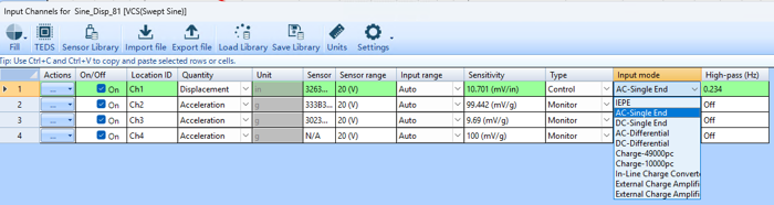
Selecting a charge input mode (Charge-49000pc, Charge-10000pc, etc.) in the Spider input channel configuration.
How Charge Mode Accelerometers Are Powered
It's easy to assume every accelerometer needs power to operate, but the two sensor families handle this very differently. An IEPE sensor requires a well-regulated constant-current supply that is typically 18 to 30 VDC, current-regulated down to a steady 2 to 4 mA for most sensors, though some call for as much as 20 mA depending on cable length needed. That current is usually delivered through a current-regulating diode or an equivalent constant-current circuit, riding on the same two wires that carry the sensor's output signal. It's worth knowing that a power supply without current-limiting will destroy an IEPE sensor almost immediately. The constant-current source isn't optional hardware, it's a requirement.
Charge mode sensors need none of this. The piezoelectric element produces its signal purely as a mechanical response: stress the crystal (shear, tension or compression), and it generates charge, with no circuit that has to be energized first. That's the whole reason charge sensors don't need a power supply at all, but it's also why the raw signal they produce can't simply be wired into a typical data acquisition input. Because it's high-impedance, it needs to be converted into a low-impedance voltage signal to be easily run through cost effective long lines and managed by common front ends. That conversion is handled either by an external charge amplifier with adjustable gain, or by a simpler in-line converter that has a fixed conversion ratio and is powered the same way an IEPE sensor would be. Which one makes sense for a given setup comes down to how much flexibility the application needs versus how simple the hardware should stay, a tradeoff Part 2 of this series gets into in detail.
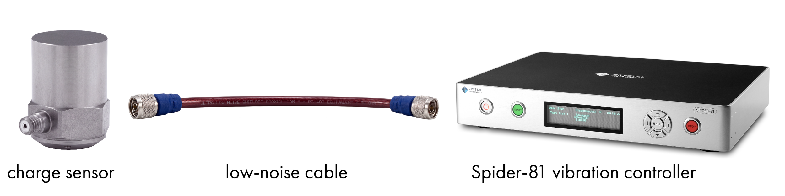
Figure 1. Using Spider built-in charge amplifier
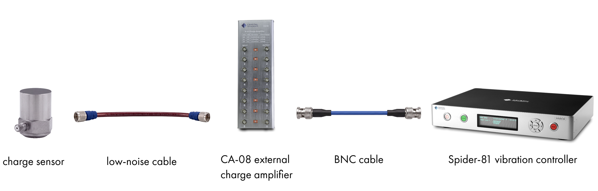
Figure 2. Using Crystal Instruments CA-08A external charge amplifier
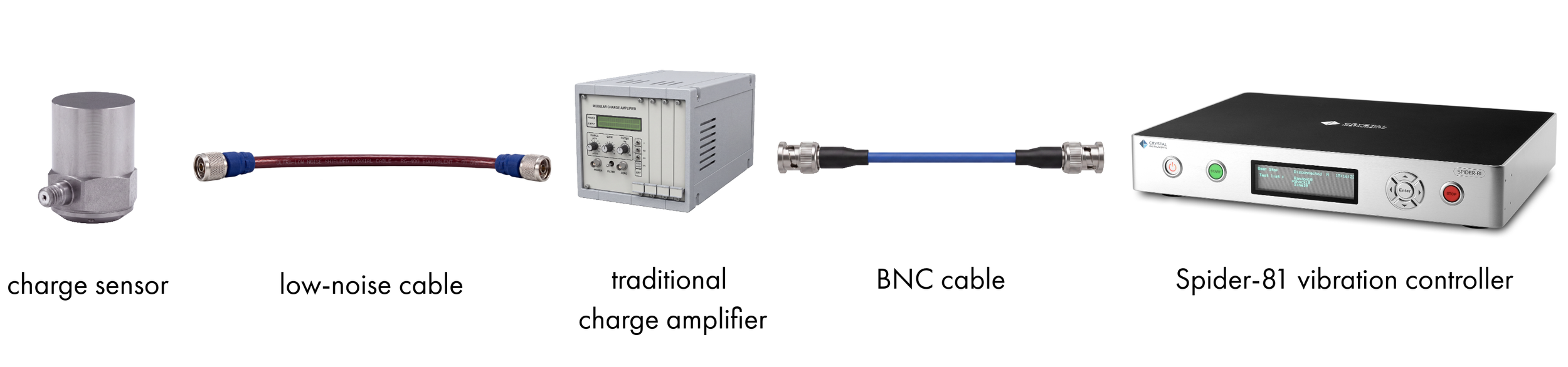
Figure 3. Using traditional charge amplifier

Figure 4. Using in-line charge converter
Understanding Measurement Range
One thing that catches people off guard with charge sensors: the range printed on the sensor's own spec sheet isn't necessarily the range you'll actually get out of a measurement. That rating describes how much charge the sensor can produce while staying linear, but that charge signal still has to pass through an amplifier or converter to become a usable voltage, and that piece of equipment has its own output ceiling.
In other words, the real limiting factor in a charge measurement chain is often the amplifier or converter, not the sensor. Set it too conservatively, and the signal clips well before the sensor itself would have maxed out. Set it too generously, and the resulting signal is so small that noise starts to dominate it. Finding where that ceiling actually sits and choosing a setting that makes good use of it, is exactly what the worked examples in Part 2 walk through.
IEPE vs. Charge Mode: Weighing the Tradeoffs
Given the choice, most general-purpose vibration testing today defaults to IEPE, and charge mode gets reserved for situations that specifically call for it. A few of the practical differences worth knowing before you pick one:
Temperature range — IEPE sensors are limited by their built-in electronics, typically –65°F to 248°F (–54°C to 120°C). Charge mode sensors are limited only by the piezoelectric material itself, commonly rated from –95°F to 1000°F (–71°C to 538°C), with specialized designs going even further.
Cable requirements — Charge sensors need low-noise, specially treated cable to resist triboelectric noise, isolation layer and EMC interference and the high-impedance signal limits the signal high frequency content upon cable length.. IEPE sensors output a low-impedance signal that travels over standard coaxial cable much farther without picking up extra noise.
Flexibility — An IEPE sensor's sensitivity and time constant are fixed at the factory; external circuits can amplify or attenuate the output but can't change what's built into the sensor. A charge amplifier, by contrast, can be adjusted in the field, including very long time constants for extending low-frequency response.
Insulation resistance and drift — At high operating temperatures, a charge sensor's insulation resistance can drop significantly, which can introduce drift in the charge amplifier and even distort the low end of the frequency response. Charge amplifiers used in high-temperature work need to be chosen specifically to tolerate a low insulation resistance (down to 10 kΩ order) without that distortion.
Cost and simplicity — IEPE systems run on comparatively inexpensive, simple signal conditioners. Charge mode systems need an external charge amplifier, and a full-featured laboratory unit is a bigger investment than a basic IEPE power supply.
For measurements that don't require extreme temperatures, this is exactly why many test engineers reach for a second IEPE accelerometer with a different range rather than deal with the added complexity of a charge amplifier. But when the application genuinely calls for high-temperature survivability, charge mode is often the only sensor that will hold up.
In Part 2 of this series, we'll put that theory to work: sizing a Spider's built-in charge amplifier, an inline charge converter, and CI's external CA-08A charge amplifier against real sensor and measurement-range numbers.